
Positioning device for a free-flying kite-type wind-attacked element in a wind-powered watercraft

a kite-like element and positioning device technology, which is applied in the direction of marine propulsion, special-purpose vessels, vessel construction, etc., can solve the problem of not being able to adjust the known apparatus

Active Publication Date: 2009-06-16
SKYSAILS GMBH & CO KG
View PDF20 Cites 27 Cited by
  • Summary
  • Abstract
  • Description
  • Claims
  • Application Information

AI Technical Summary

Benefits of technology

[0004]A positioning apparatus for a freely flying kite-like element on which wind acts, having a wing profile as the exclusive drive, as an auxiliary drive or as an emergency drive, which is connected via a hawser to a watercraft, in particular to a sea-going vessel, can be achieved advantageously by in each case matching the length of the hawser to the atmospheric conditions. If automatic paying-out and pulling-in are intended to be provided, then the limit force for paying out is set to be higher than the limit force for pulling in, thus resulting in stable operation without control oscillations.
[0033]If additional storage means and comparator means are provided which allow storage of signals associated with previous times together with signals which appear at later times, in such a manner that successive maneuver states can be compared, it is possible to provide predictive control of the element on which wind acts in the sense that the predictable consequences for vessel operation are taken into account on initiation of a maneuver.

Problems solved by technology

However, this does not relate to a winch which is suitable for adjustment of an element on which wind acts, in accordance with the wind conditions, for a watercraft with wind propulsion, but relates only to keeping a general aeronautical object at a constant height.
It is not possible to adjust the known apparatus on the basis of the wind conditions.

Method used


Image

  • Positioning device for a free-flying kite-type wind-attacked element in a wind-powered watercraft
  • Positioning device for a free-flying kite-type wind-attacked element in a wind-powered watercraft
  • Positioning device for a free-flying kite-type wind-attacked element in a wind-powered watercraft

Examples


Embodiment Construction

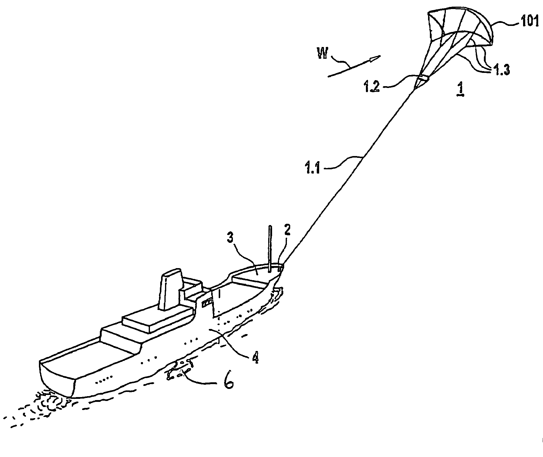
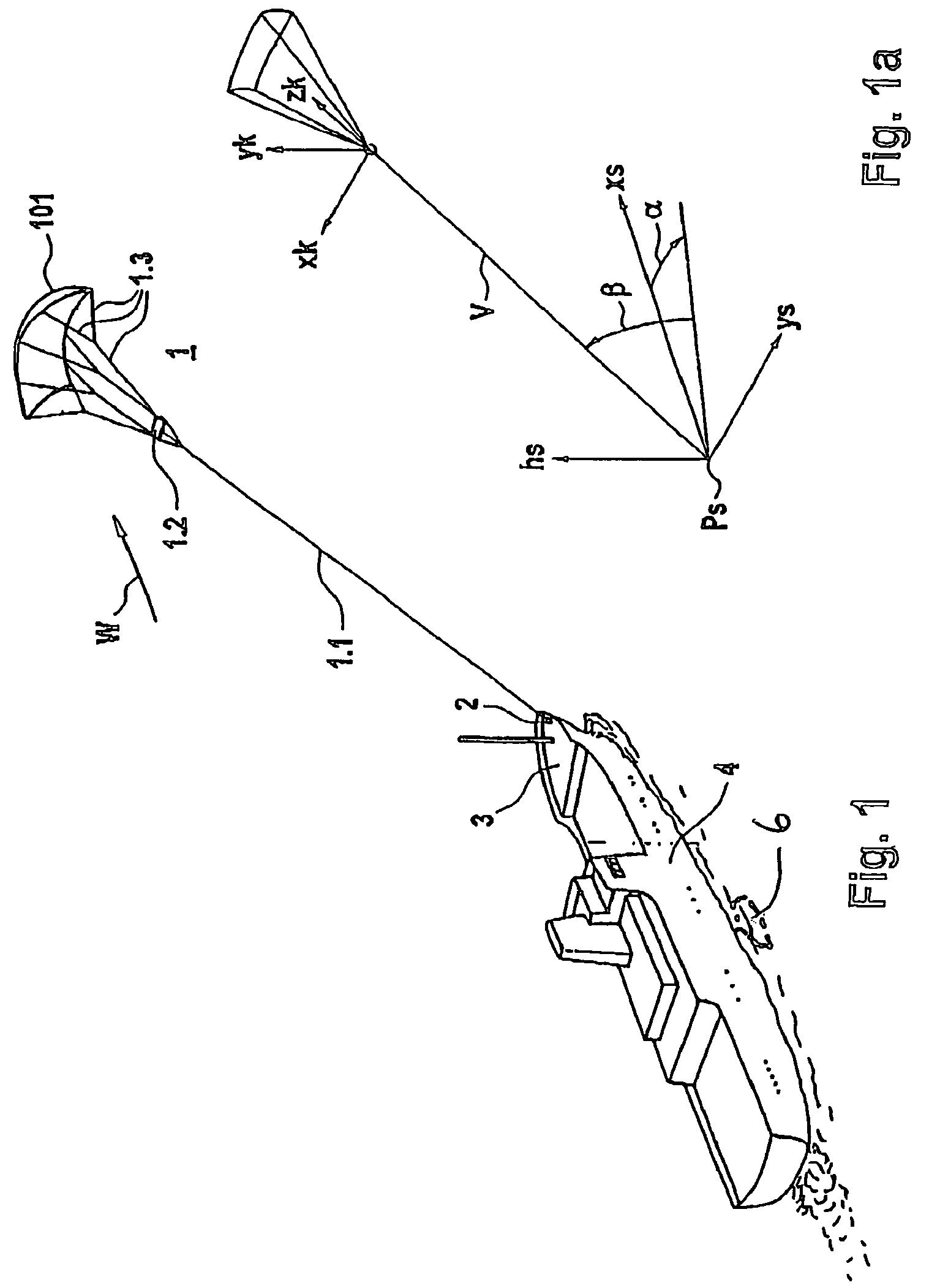
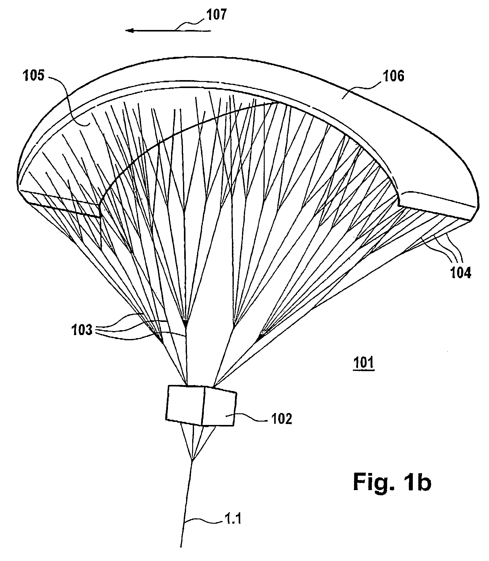
[0046]FIG. 1 shows an oblique plan view of a vessel which is being towed by the kite system. In this case, an element 1 on which wind acts is connected to a vessel 4 via a hawser 1.1 with an apparatus 2 on which force acts and which is provided in the bow area of the vessel 4. The hawser 1.1 is passed to a central gondola 1.2, from which a number of holding lines 1.3 originate, which are passed to, the element 1 on which wind acts and is in the form of a paraglider with a kite profile, giving it the necessary shape. The details relating to this will be explained further below in the description. The apparent wind direction in the area of the element 1 on which wind acts is annotated W. The corresponding wind vector is indicated by its magnitude and direction. If required, its rate of change is also indicated by a variable B, which denotes the gusting, forms the mean time discrepancy between the wind speed and its mean value and can be represented as a scalar, which effectively forms...


PUM


Abstract

Disclosed is a positioning device for a free-flying kite-type wind-attacked element that comprises a profiled wing, is used as the exclusive, an auxiliary, or an emergency drive unit, and is connected to a watercraft via a traction rope. The positioning device is provided with a winch that can cause the traction rope to be taken in when a given first tractive force is not attained and / or when the flow is about to stop or has stopped abruptly and / or cause the traction rope to be veered when given a second tractive force and / or a given inflow velocity are / is exceeded.

Description

BACKGROUND OF THE INVENTION[0001]The invention relates to a positioning apparatus for a freely flying kite-like element on which wind acts for a watercraft with wind propulsion.[0002]A positioning apparatus such as this is known from U.S. Pat. No. 2,433,344. However, this does not relate to a winch which is suitable for adjustment of an element on which wind acts, in accordance with the wind conditions, for a watercraft with wind propulsion, but relates only to keeping a general aeronautical object at a constant height. It is not possible to adjust the known apparatus on the basis of the wind conditions.SUMMARY OF THE DISCLOSURE[0003]A positioning apparatus of the generic type indicated initially which does not have the stated disadvantage allows the position of the element on which wind acts to be adapted automatically in accordance with the wind conditions.[0004]A positioning apparatus for a freely flying kite-like element on which wind acts, having a wing profile as the exclusive...

Claims


Application Information

Patent Timeline
IPC IPC(8): B63H9/06
CPCB63H9/0685B63H2009/0692B63H9/072B63H9/071Y02T70/5236B63B2035/009
Inventor WRAGE, STEPHAN
Owner SKYSAILS GMBH & CO KG
Learn More