Method and device for full thickness resectioning of an organ
a full-thickness resection and organ technology, applied in the direction of surgical staples, surgical forceps, paper/cardboard containers, etc., can solve the problems of long recovery time, partial or complete loss of mobility, and painful incisions,
- Summary
- Abstract
- Description
- Claims
- Application Information
AI Technical Summary
Benefits of technology
Problems solved by technology
Method used
Image
Examples
first embodiment
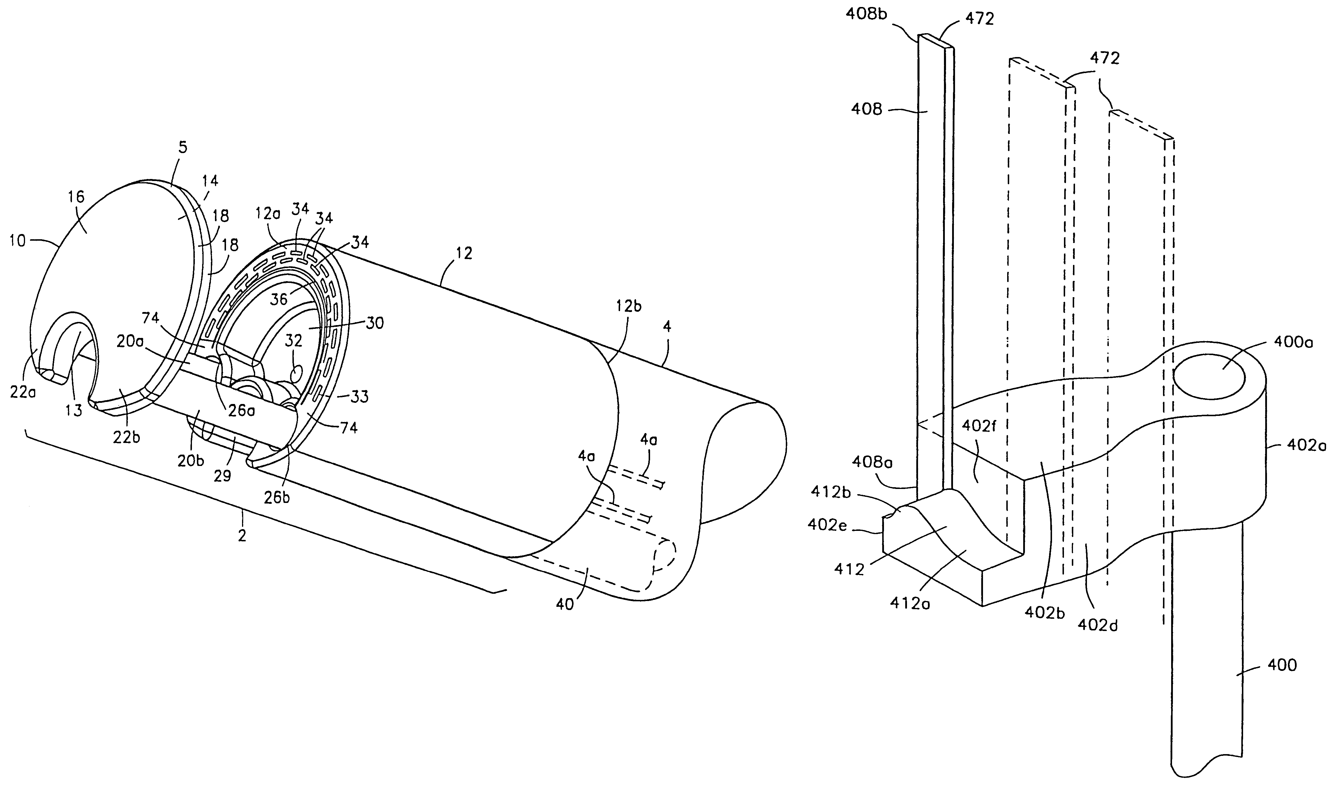
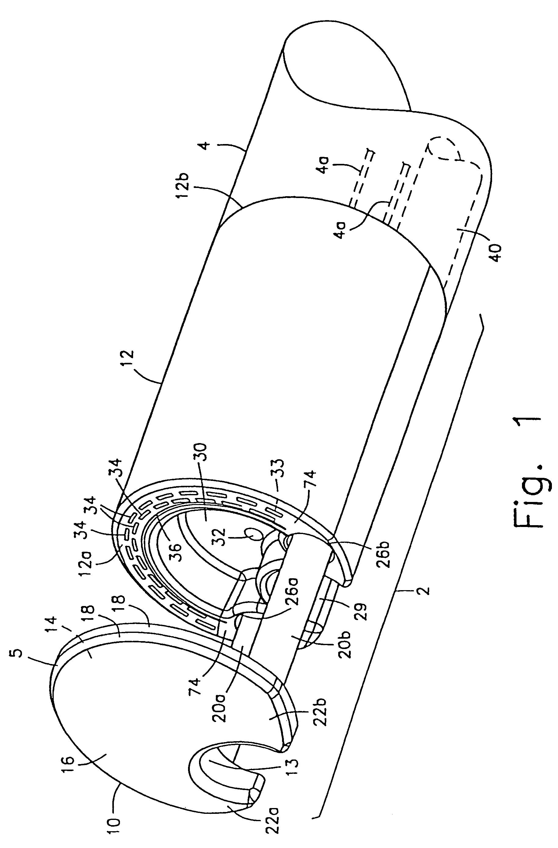
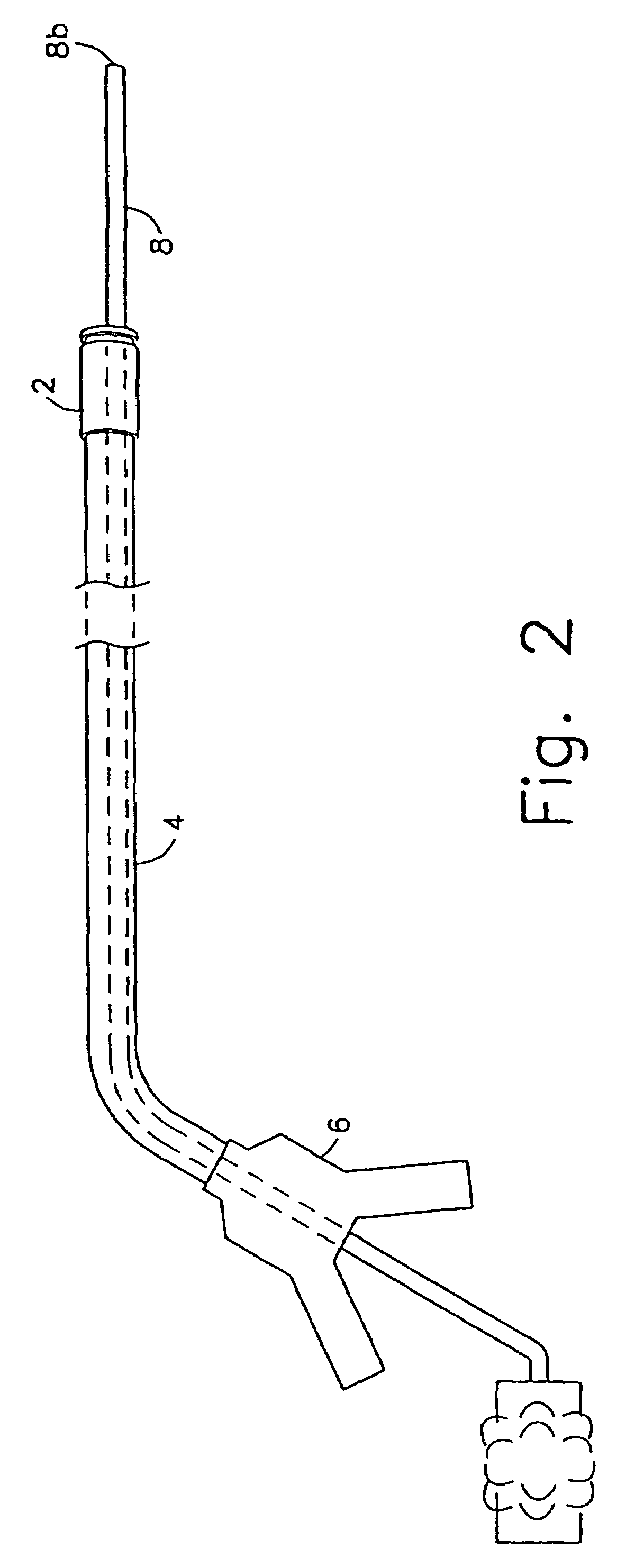
[0043]As shown in FIGS. 1 and 2, an apparatus according to the present invention comprises a working head assembly 2 which may preferably be connected to a distal end 4a of a sheath 4. The proximal end 4b of the sheath 4 may preferably be connected to a control handle 6.
[0044]In operation, the entire apparatus is mounted onto an endoscope 8 by passing the endoscope 8 through the control handle 6, the sheath 4, and the working head assembly 2, as shown in FIG. 2. The endoscope 8 is then inserted into a body orifice to locate a lesion in the tubular organ under visual observation (usually while insufflating the organ). Once the lesion has been located, the working head assembly 2 and the sheath 4 are slidably advanced along the endoscope 8 into the tubular organ until the working head assembly 2 is in a desired position adjacent to the lesion. Those skilled in the art will understand that in an alternative embodiment, the working head assembly 2 may also be detachably coupled to a dis...
second embodiment
[0077]FIG. 11 shows a device according to the present invention in which like reference numerals identify the same elements.
[0078]The anvil member 10 of this embodiment preferably has a substantially circular or elliptical cross-section and is gradually tapered from the proximal face 14 to its distal end 16, forming a bullet-like structure. This tapered shape allows the device to be more easily inserted into the patient's body as the distal end 16 has a smaller cross-sectional size than in the first embodiment. Those skilled in the art will understand that the anvil member 10 may have other tapered shapes besides a bullet-like structure without departing from the scope of the present invention.
[0079]Instead of providing the cut-out 13 shown in the first embodiment to receive the endoscope 8 therein, a substantially cylindrical first endoscope lumen 13 extends axially through the center of the anvil member 10. The distal end 16 of the anvil member 10 may preferably have a beveled edg...
third embodiment
[0084]FIG. 12 shows a device according to the present invention. The proximal face 14 of the anvil member 10 of this embodiment has a cross-section similar to the crescent-shaped cross-section of the anvil member 10 of the device of FIG. 1. Thus, the anvil member 10 has two horns 22a and 22b formed on either side of a cut-out 13 which extends axially through the anvil member 10 from the proximal face 14 to the distal end 15 to receive the endoscope 8 therein. As with the device of FIG. 11, the cross-sectional size of the anvil member 10 diminishes in overall size from a maximum at the proximal face 14 to a minimum size at the distal end 15, and the horns 22a and 22b become less pronounced from the proximal face 14 to the distal end 15. In a side view, the anvil member 10 becomes gradually tapered from the proximal end 14 to the distal end 16.
[0085]As in the device of FIG. 11, the tapered shape of the anvil member 10 of the device of FIG. 12 allows for easier insertion of the device ...
PUM
 Abstract
Description
Claims
Application Information
 - R&D
- Intellectual Property
- Life Sciences
- Materials
- Tech Scout
- Unparalleled Data Quality
- Higher Quality Content
- 60% Fewer Hallucinations
Browse by: Latest US Patents, China's latest patents, Technical Efficacy Thesaurus, Application Domain, Technology Topic, Popular Technical Reports.
© 2025 PatSnap. All rights reserved.Legal|Privacy policy|Modern Slavery Act Transparency Statement|Sitemap|About US| Contact US: help@patsnap.com


