Wheel covering system

a technology for ornamental covers and wheels, applied in the direction of wheel protection, vehicle components, hubs, etc., can solve the problems of affecting the integrity of the wheel attachment structure, the device and the method used to attach ornamental covers to the wheels of large vehicles, and the denial of insurance coverage, etc., to achieve the effect of convenient attachmen

Inactive Publication Date: 2009-06-16
PRESTIGE AUTOTECH CORP
View PDF70 Cites 29 Cited by
  • Summary
  • Abstract
  • Description
  • Claims
  • Application Information

AI Technical Summary

Benefits of technology

[0008]According to a preferred embodiment of the invention, there is described a wheel covering system that provides a sturdy and robust system for attaching an ornamental wheel cover over a wheel of a large vehicle such as a truck or rig, coverable of withstanding the kind of impact load that a wheel cover might experience over its lifetime, yet being easy to attach, and avoiding connection with the wheel attachment system of the axle hub.
[0010]In a further aspect, the wheel covering system includes a feature in which the ornamental cover has a third hole at the center point, and the proximal end of the mounting member includes a spindle positioned to be inserted through the third hole. Preferably, the spindle may be longer than the flanking studs. Thus, the spindle advantageously facilitates attachment of the cover over the wheel because, when the mounting member has been attached to the hub, it permits the operator to slip the cover over the spindle first, then, by rotating the cover somewhat, to match the two offset holes in the cover with the studs and push the cover over the spindle and studs. The central hole may have a conical portion to facilitate this action. The studs and spindle provide a high degree of redundancy to secure the connection and provide a factor of safety against rotational and shear forces that may be exerted during braking or in a collision.
[0011]In other aspects of the covering system, the ornamental cover has a recess for housing the studs. A bolt-on cap closes off the recess, providing a smooth outer surface to the cover when completely mounted. Preferably, the recess has a floor that is flat, and the proximal end of the mounting member is flat. Thus, the floor of the recess is configured to be compressed against the proximal end of the mounting member by nuts screwed onto the threaded studs, and this provides a secure and wobble free attachment of the cover to the mounting member.
[0012]In one embodiment of the invention, principally for steering and trailing axles, the mounting member includes a cylindrical portion, an external flange attached to the distal end of the mounting member, and a circular plate attached to the proximal end of the mounting member. Preferably, the cylindrical portion is between 3 and 4 mm thick, to provide a sufficiently light but robust mounting member for connecting the cover to hub. A plurality of holes are formed in the flange to receive the hub cap bolts, whereby both the mounting member and the hub cap may be attached to the hub, the mounting member covering the hub cap. The threaded studs are attached to the circular plate at the proximal end of the mounting member. Preferably, the mounting member includes a slot configured to receive a valve of the hub cap. In this way, the oil or grease level may be maintained without removing the mounting member from the hub. Additionally, the mounting member may include an orifice positioned to allow inspection, through the mounting member, of the oil or grease level in the hub cap. Thus, the oil or grease level may be checked without removing the mounting member from the hub.
[0013]In a second embodiment, principally for drive axles, the mounting member is configured to provide attachment of an ornamental cover to a hub having an axle mounting cap. The mounting member of this embodiment also does not contact threaded lugs on the hub that are intended for attaching a wheel to the axle. However, here, the mounting member is formed from an initially flat plate having two ends. The plate is bent to a configuration adapted to span across the axle mounting cap and to be fixed to the axle mounting cap at the two ends. In this embodiment, the thickness of the plate is preferably between 4 mm and 5 mm to provide desirable stiffness and strength. This configuration also overcomes shortcomings in the prior art, and provides a sufficiently robust configuration for a wheel covering system that can be expected to experience impact loads during its lifetime.

Problems solved by technology

Unfortunately, the devices and methods used to attach ornamental cover assemblies over the wheels of large vehicles suffer from various shortcomings.
Although this method uses structure present on the vehicle which is clearly intended for affixation of structure (such as a wheel), the method has the disadvantage of making the integrity of the wheel attachment structure dependent upon the viability of a foreign structure that was not part of the vehicle manufacturer's original wheel attachment design.
The addition of foreign structure to the original wheel attachment assembly may lead to shortcomings, and indeed, may lead to denial of insurance coverage where the shortcomings are attributable to structure foreign to the original vehicle design.
Additional problems may arise should the vehicle be subject to inspection by local, state, or federal authorities.
Removal of the covers may require the vehicle to be jacked up, on a wheel by wheel basis, to take the load off each wheel while the covers are being removed, causing considerable inconvenience.
However, a shortcoming in the foregoing structure is that it is flimsy, in that an impact on the ornamental wheel cover may permanently bend or buckle the rods out of original alignment, leaving the wheel cover in a disfigured spatial relationship to the wheel, defeating the purpose of the ornamentation.
It has been found that a wheel cover having such a large weight may suffer from inadequate torsional and shear attachment to the wheel hub where insufficient attachment means are provided.
Where a single central stud is provided for attachment, the rotational momentum of a heavy wheel cover may cause the cover to incline to rotate independently when the vehicle is brought to a sudden stop, because the wheel cover does not have its own braking system and may not be connected over the wheel other than at a central stud.
Added to the problem of rotational momentum may be the problem of shear, which may be additionally incurred when the cover is impacted by collision with a curb, bollard or the like.

Method used


Image

  • Wheel covering system
  • Wheel covering system
  • Wheel covering system

Examples


first embodiment

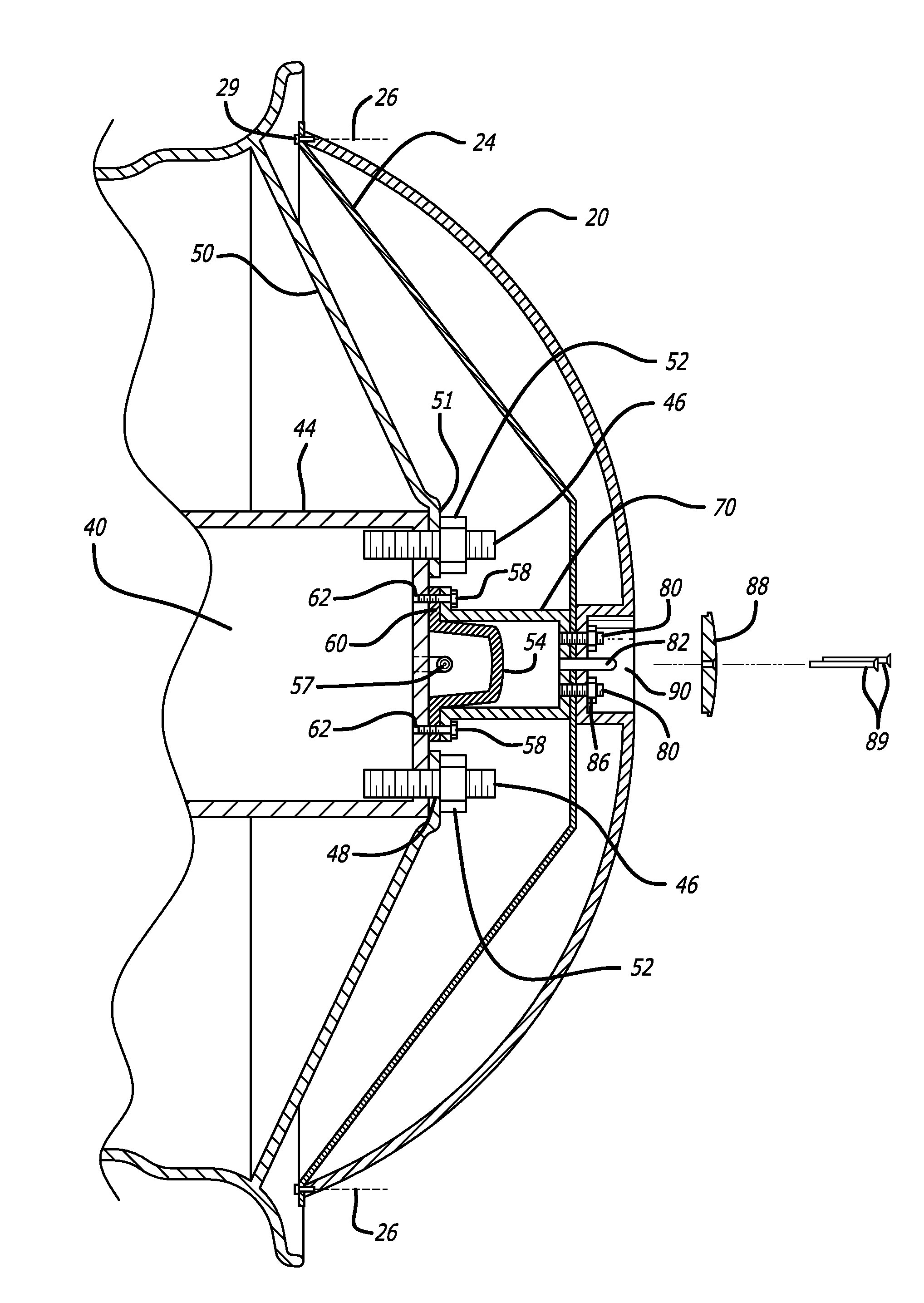
[0029]Turning now to a wheel cover assembly of the present invention, as best seen in FIG. 5, an ornamental outer cover adapted for attachment according to the present invention is generally indicated by the numeral 20. Where the cover 20 is intended for attachment to a large vehicle such as a truck or rig, it is beneficially made of cast aluminum, and may weigh as much as about 15 to 30 pounds. This substantial weight gives the cover 20 considerable durability, able to withstand the occasional impact that is inevitable over the lifetime of a cover.

[0030]In a preferred embodiment, the cover 20 has openings (not shown in the figures) that give the cover a visible depth to one viewing the cover attached to a wheel. To enhance this visible depth, a second cover element is provided, being a foil sheet 24 specially made to have enhanced reflective properties on one side, preferably out of aluminum or stainless steel and in the range of 0.5 to 1 mm thick. The foil sheet 24 is placed dista...

second embodiment

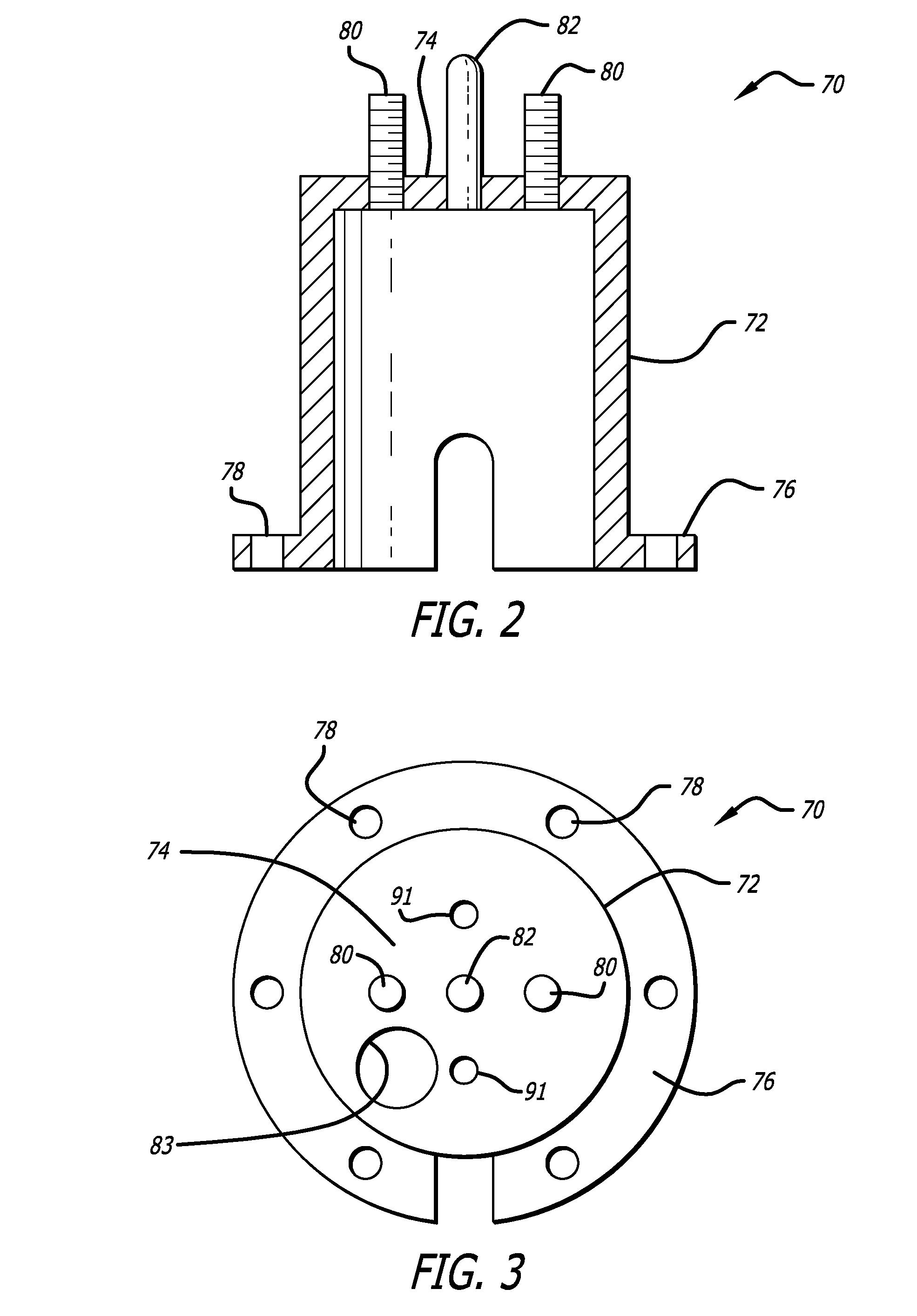
[0044]The mounting member 70′ in this second embodiment is exemplified best in FIGS. 7-8. The mounting member is not formed from a cylinder as in the previous embodiment, but in this case may be fabricated from a flat metal plate which is then bent to a shape suitable for spanning over a bulbous axle cap 54′ covering the driving wheel hub 44′, as exemplified in FIGS. 7-8, and 10. Preferably, as in the previous embodiment, the proximal surface 74′ of the mounting member is flat, and vertical, when in use. In a preferred embodiment, the thickness of the flat metal plate is between 5 and 6 mm, to provide suitable stiffness and strength without excessive weight. The extremities of the plate may be shaped to conform to the circular perimeter of the hub 44′. Holes 78′ are provided in the extremities of the plate and positioned to match locations of the axle cover bolts 58′ holding down the bulbous axle cap 54′ on the hub. The mounting member 70′ of this embodiment similarly includes two t...


PUM


Abstract

A wheel covering system is disclosed having a first external cover element and a second internal cover element screwed to the first element. The wheel covering system is connected to an hub of a large vehicle such as a truck without relying on lugs provided on the hub for connecting the wheel to the hub. The connection is achieved by relying on bolts used to attach a hub cap (or axle cover) to the axle, without eliminating the hub cap (or axle cover), and at the same time providing a sturdy and robust connection capable of withstanding forces expected to be applied to a wheel cover during its lifetime.

Description

BACKGROUND OF THE INVENTION[0001]The present application relates to ornamental wheel covers, in particular to wheel cover assemblies that are suitable for affixing to vehicles such as heavy trucks, or rigs, and the like.[0002]The motor vehicular transport industry today is a vibrant part of the economy, and many large transport trucks and rigs are privately owned. Indeed, many a large rig is the effective home of its private owner, providing onboard computers, communication systems, televised entertainment, and sleeping quarters. Ornamentation of the exterior has become an important aspect of personal ownership. Accordingly, the fitting of ornamental wheel covers over the wheels of large rigs and trucks has become widespread in recent years.[0003]Unfortunately, the devices and methods used to attach ornamental cover assemblies over the wheels of large vehicles suffer from various shortcomings. Commonly, some devices for attaching ornamental covers over wheels have relied upon outwar...

Claims


Application Information

Patent Timeline
Patent Type & Authority Patents(United States)
IPC IPC(8): B60B7/14B60B27/00
CPCB60B7/20
Inventor NECAISE, RONALD
Owner PRESTIGE AUTOTECH CORP
Why Eureka
Try Eureka