Structure of electrical connector

a technology of electrical connectors and connectors, applied in the direction of coupling device connections, connection contact member materials, coupling protection earth/shielding arrangements, etc., can solve the problems of electrical connector signal interference, signal transmission error or failure, etc., to avoid damage

Inactive Publication Date: 2009-06-16
U D ELECTRONIC CORP
View PDF6 Cites 20 Cited by
  • Summary
  • Abstract
  • Description
  • Claims
  • Application Information

AI Technical Summary

Benefits of technology

[0010]According to another aspect of the present invention, the circuit board is provided with at least one passive component, filter, surge arrester or any other grounding or EMI protection component to effective remove noises from the transmitting signal, avoiding damage.

Problems solved by technology

However, the problem of electromagnetic interference must be taken into account when designing a small-sized electrical connector for computer.
Signal interference of an electrical connector may come from external electromagnetic waves or the inside noises.
During operation of an electrical connector, external electromagnetic waves from an external transmission line may interfere with the transmission of power supply or signal in the electrical connector, and this interference may affect the surrounding electronic components or circuits, causing a signal transmission error or failure or affecting the signal transmission quality of the electrical connector.
However, the installation of a filter device in a circuit board is complicated and requirements much installation space.
This spring strip formation procedure complicates the fabrication of the metal shield and wastes much the metal material.
However, the arrangement of filter module and / or grounding terminals complicates the circuit layout of the electrical connector.
Further, arranging multiple grounding terminals and signal terminals in the limited surface area of a circuit board for electrical connector may cause electromagnetic interference among the terminals, lowering signal transmission stability and the shielding effect of the metal shield.

Method used


Image

  • Structure of electrical connector
  • Structure of electrical connector
  • Structure of electrical connector

Examples


Embodiment Construction

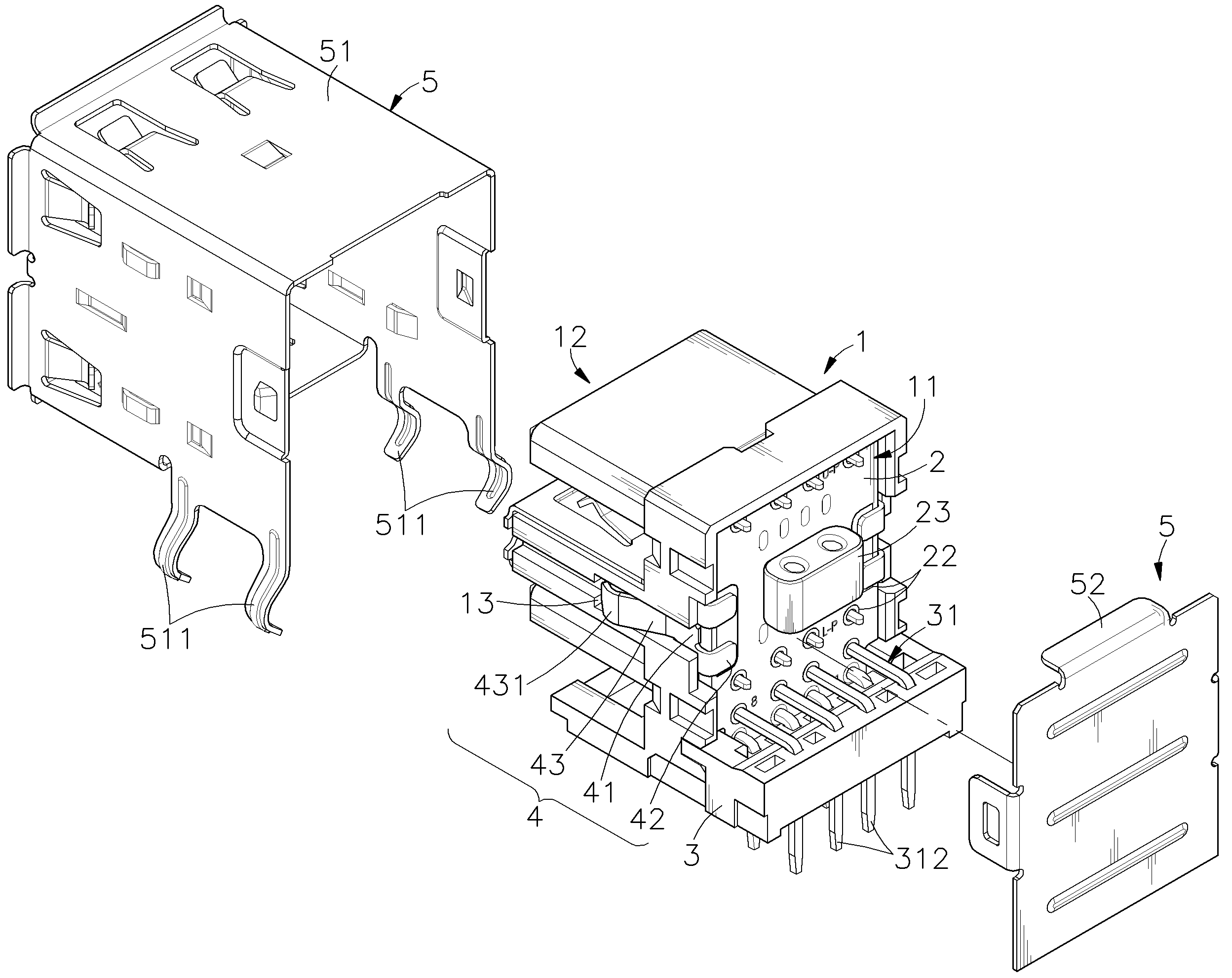
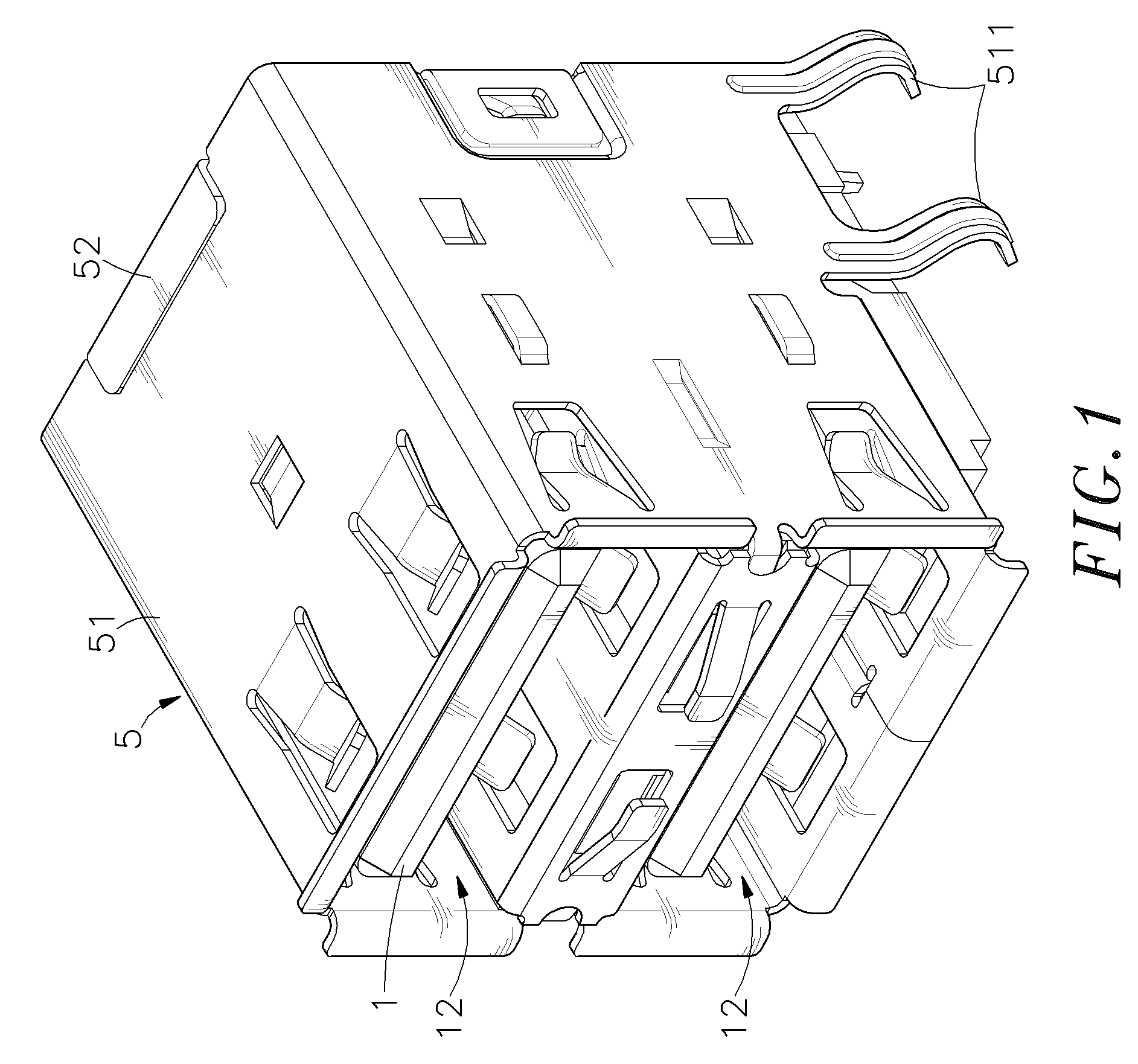
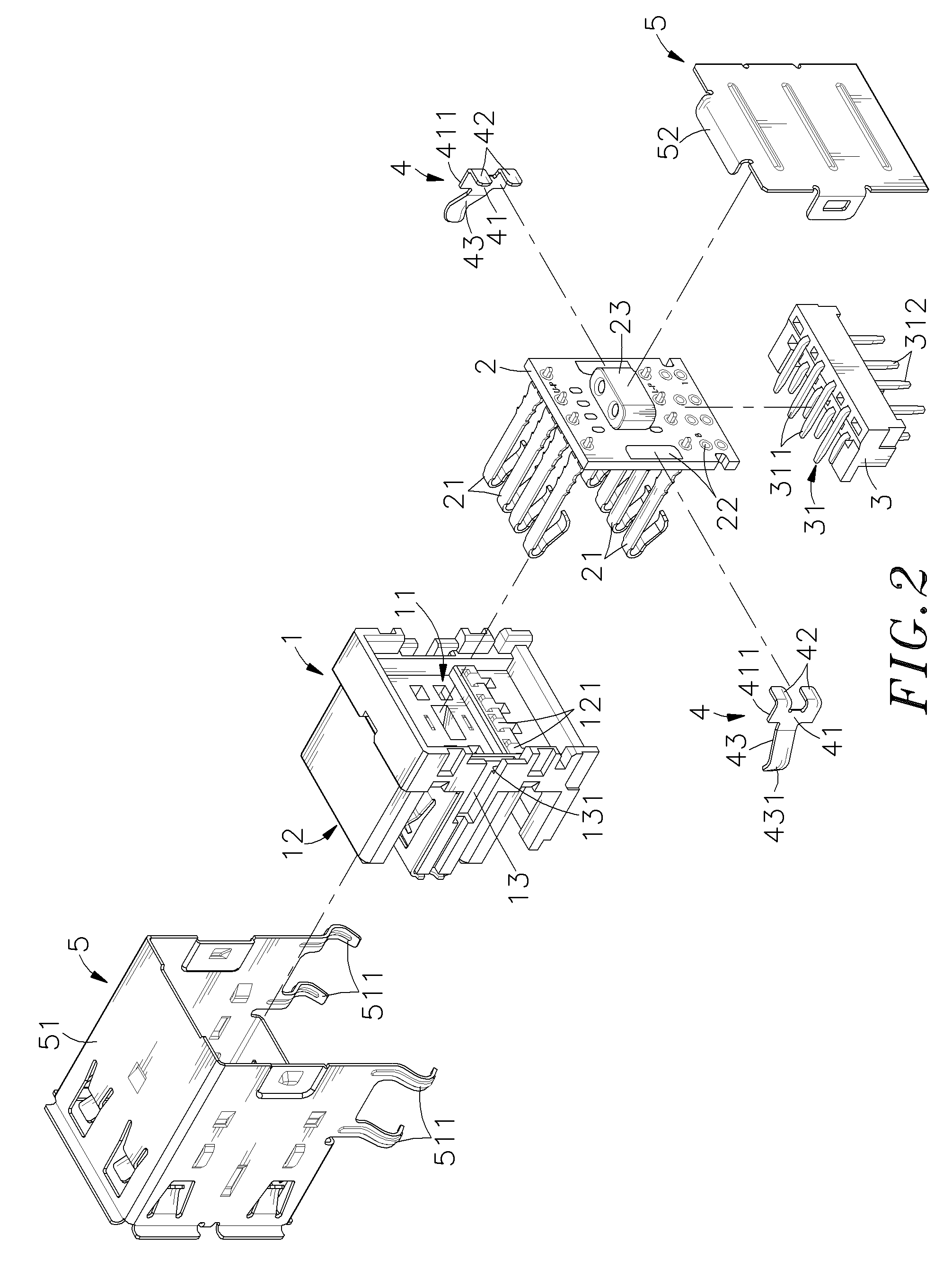
[0017]Referring to FIGS. 1˜3, an electrical connector in accordance with the present invention is shown comprised of an electrically insulative housing 1, a circuit board 2, an adapter module 3, a plurality of, for example, two grounding spring plates 4 and a metal shield 5.

[0018]The electrically insulative housing 1 comprises a rear accommodation space 11 defined in a rear side thereof, a front receiving unit 12 disposed at a front side thereof for receiving a matching electrical connector (not shown), a plurality of terminal slots 121 formed in the front receiving unit 12 and backwardly extending to the rear accommodation space 11, two recessed locating portions 13 symmetrically disposed at two opposite lateral sides thereof, and two mounting grooves 131 respectively backwardly extending from the recessed locating portions 13 to the rear side.

[0019]The circuit board 2 is mountable in the rear accommodation space 11 of the electrically insulative housing 1, comprising a plurality o...


PUM


Abstract

An electrical connector includes an electrically insulative housing that has a rear accommodation space, a front receiving unit for receiving a matching electrical connector, terminal slots formed in the front receiving unit and extended to the rear accommodation space and recessed locating portions symmetrically disposed at two opposite lateral sides, a circuit board mounted in the rear accommodation space of the housing and having signal terminals extended from the front side thereof and respectively inserted into the terminal slots of the housing and suspending in the front receiving unit of the housing, an adapter module fastened to the rear bottom side of the circuit board and carrying a plurality of input terminals that have the respective front connection portions respectively electrically connected to the metal contacts of the circuit board and the respective rear bonding portions downwardly extending out of the bottom wall of the adapter module for bonding to an external circuit board, grounding spring plates respectively mounted in the recessed locating portions of the housing and bonded to the circuit board for grounding, and a metal shield surrounding the housing and the adapter board and kept in positive contact with the grounding spring plates for grounding.

Description

[0001]This application claims the priority benefit of Taiwan patent application number 096215544 filed on Sep. 14, 2007.BACKGROUND OF THE INVENTION[0002]1. Field of the Invention[0003]The present invention relates to electrical connectors and more particularly, to an improved structure of electrical connector, which has grounding spring plates mounted in recessed locating portions at two opposite sides of the electrically insulative housing and bonded to the circuit board that is mounted in a rear accommodation space in the rear side of the electrically insulative housing for grounding to avoid electromagnetic wave interference.[0004]2. Description of the Related Art[0005]Following fast development of computer technology, versatile desktop computers as well as notebook computers have been continuously created. These advanced computers have the characteristics of strong computing function, fast operating speed, small size and high transmission speed. The most popularly used USA conne...

Claims


Application Information

Patent Timeline
Patent Type & Authority Patents(United States)
IPC IPC(8): H01R12/00
CPCH01R13/502H01R13/65802H01R12/712H01R25/006H01R13/6658H01R13/6616H01R13/6625H01R13/6666H01R13/719H01R13/6582
Inventor LIN, HUNG-CHAO
Owner U D ELECTRONIC CORP
Why Eureka
Try Eureka