Pulse width modulated buck voltage regulator with stable feedback control loop

a voltage regulator and feedback control technology, applied in the field of pulse width modulated buck voltage regulators, can solve the problems of increasing the complexity and cost of external components of pwm buck regulators, reducing the efficiency of buck voltage regulators, and increasing the ripple at output voltages. the effect of hardware minimization

Active Publication Date: 2009-06-16
MARVELL ASIA PTE LTD
View PDF20 Cites 51 Cited by
  • Summary
  • Abstract
  • Description
  • Claims
  • Application Information

AI Technical Summary

Benefits of technology

[0010]In accordance with one embodiment of the present invention, both the duty cycle and the frequency of an output voltage signal are regulated by a PWM buck regulator. To achieve this, the output voltage is compared with first and second reference voltages. If the output voltage is detected as being greater than the first reference voltage, a counter's count is decremented with each transition of a clock signal. If the output voltage is detected as being less than the second reference voltage, the counter's count is incremented with each transition of the clock signal. The counter is disabled if the output voltage is detected as being smaller than the first reference vo

Problems solved by technology

Therefore, frequency compensator 120 is typically difficult to design and often requires components external to PWM buck regulator 100 if the external load seen by node 135 is not purely resistive.
Such external components increase both the complexity as well as the cost of PWM buc

Method used


Image

  • Pulse width modulated buck voltage regulator with stable feedback control loop
  • Pulse width modulated buck voltage regulator with stable feedback control loop
  • Pulse width modulated buck voltage regulator with stable feedback control loop

Examples


Embodiment Construction

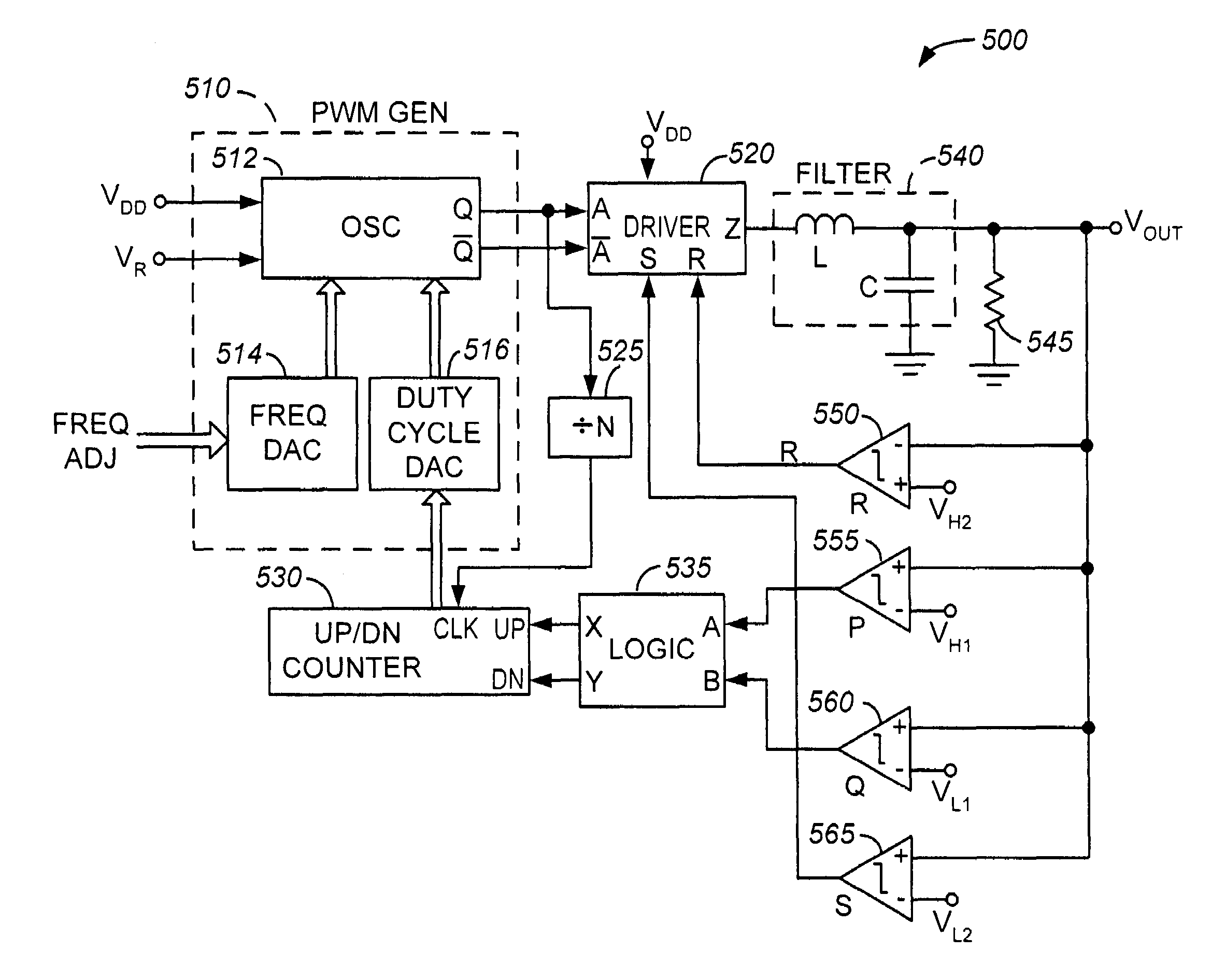
[0040]FIG. 6 is a simplified high-level block diagram of a PWM buck regulator 400, in accordance with one embodiment of the present invention. PWM buck regulator (hereinafter alternatively referred to as regulator) 400 is shown as including, in part, a pulse-width modulated signal generator 410, a driver 420, a divider 425, an up / down counter 430, and a voltage comparator 435.

[0041]If output voltage VOUT is greater than reference voltage VR, comparator 435 generates a logic low signal causing up / down counter to be placed in the countdown mode. When placed in the countdown mode, with each rising or falling transition of clock signal Clk, counter 430's count is decremented, thereby decreasing the duty cycle of signal A generated by pulse-width modulated signal generator 410. Counter 430 continues to count down continues until voltage VOUT falls below reference voltage VR. When voltage VOUT is less than reference voltage VR, comparator 435 generates a logic high signal causing up / down ...


PUM


Abstract

A pulse-width modulated buck regulator includes a feedback control without having any external frequency compensation components to stabilize the feedback control loop irrespective of the reactive component of its load impedance. Additionally, the output voltage is maintained constant not only with feedback but also using a power supply voltage compensation scheme. Thus, the feedback control compensates for resistive losses, thus minimizing hardware. The output voltage is compared with first and second reference voltages. If the output voltage is greater than the first reference voltage, a counter's count is decremented. If the output voltage is less than the second reference voltage, the counter's count is incremented. The counter is disabled if the output voltage is smaller than the first reference voltage and greater than the second reference voltage. The duty cycle of the output voltage is varied in accordance with the counter's count.

Description

CROSS-REFERENCES TO RELATED APPLICATIONS[0001]The present application claims benefit under 35 USC 119(e) of U.S. provisional application No. 60 / 677,779, filed May 3, 2005, entitled “PWM Buck Regulator With Minimal Feedback Control Range”, the content of which is incorporated herein by reference in its entirety.BACKGROUND OF THE INVENTION[0002]The present invention relates to electronic circuits, and more particularly to conversion of supply voltages used in such circuits.[0003]In integrated circuits (IC), there is often a need to generate a lower DC voltage from a higher DC supply voltage. One known circuit for achieving this is commonly referred to as pulse width modulated (PWM) buck regulator, a simplified block diagram of which is shown in FIG. 1. PWM buck regulator 100 of FIG. 1 is shown as including, in part, a PWM signal generator 105, a driver 110, and an analog feedback control loop 115. Feedback control loop 115, in turn, includes a comparator 125, and a frequency compensat...

Claims


Application Information

Patent Timeline
IPC IPC(8): G05F1/00
CPCH02M3/156
Inventor DASGUPTA, UDAYKURNIAWAN, RUDYZHANG, YAYUE
Owner MARVELL ASIA PTE LTD
Why Eureka
Try Eureka