Tower of a wind power installation

a technology of wind power installation and tower, which is applied in the direction of sustainable buildings, structural elements, building components, etc., can solve the problems of increasing the bonding material, affecting the erection of the pylon, and taking a long time to harden, so as to speed up the construction of the pylon

Inactive Publication Date: 2009-06-23
WOBBEN ALOYS
View PDF18 Cites 8 Cited by
  • Summary
  • Abstract
  • Description
  • Claims
  • Application Information

AI Technical Summary

Benefits of technology

[0006]One object of the invention is to speed up construction of a pylon comprising segments disposed in mutually superposed relationship, with a bonding material between the segments.
[0009]If a high current, for example in the range of 70 to 150 A, flows through such a wire, then the wire heats up and the bonding material applied to the top side of the segment can harden quickly in the desired manner, in spite of cold outside temperatures.
[0010]To achieve a good heating effect, it is advantageous if the heating module is provided over the entire surface area within the upper region of a concrete segment in order to achieve maximum possible transmission of heat to the bonding material.

Problems solved by technology

Under some circumstances however a problem can arise with the bonding material when the pylon is erected at a cold time of the year.
More specifically, the bonding material usually requires a minimum temperature for it to harden and, if the outside temperature is low, for example around 0° C., either the bonding material does not harden or hardening takes a very long period of time, which considerably delays total erection of the pylon.

Method used


Image

  • Tower of a wind power installation
  • Tower of a wind power installation
  • Tower of a wind power installation

Examples


Embodiment Construction

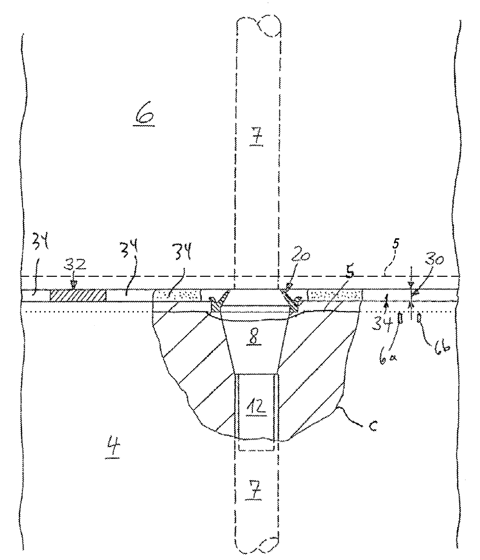
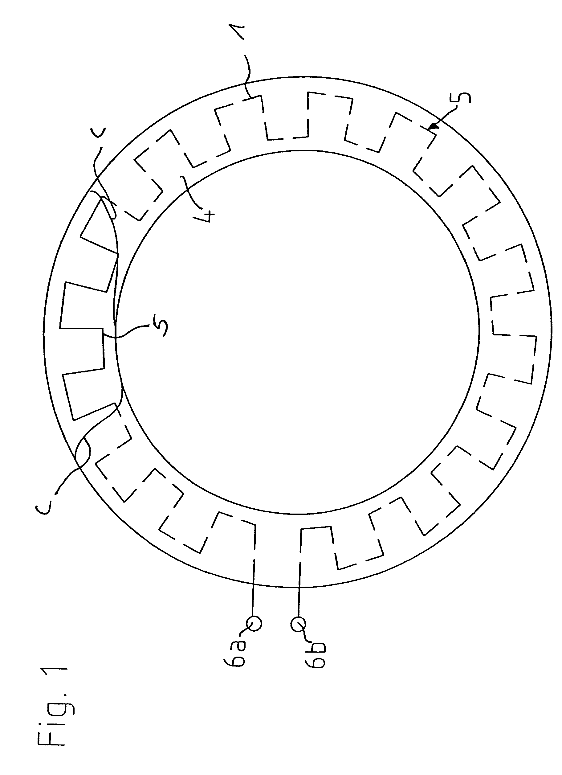
[0017]FIG. 1 shows a round pylon segment 4, viewing from above with a cut-away cross-section at line c-c removed from the surface of a pylon segment. It is to be seen in this respect that a heating module 1 is positioned in the upper region 2 of the pylon segment, the heating module comprising a heating wire 5 which is disposed in a meander configuration within the concrete segment 4, as shown. It is also possible to see two connecting terminals 6a, 6b for the heating wire 5, to which it is possible to connect for example a welding transformer which generates a high current which can be passed through the heating wire 5 so that the heating wire 5 is heated and then also provides for heating the concrete in the uppermost region of the segment so that the bonding material on the segment can harden.

[0018]FIG. 4 shows a completed pylon 10 being composed of a plurality of segments labeled generally S. Some of the segments are labeled to specific reference numbers, such as segments 2, 4, ...


PUM


Abstract

There are various pylons of wind power installations, primarily lattice mast pylons, tubular steel pylons or concrete pylons. In the case of pylons of concrete, there are various possible ways of producing same, inter alia also erecting pylons from ready-made reinforced concrete parts, wherein the individual ready-made reinforced concrete parts form respective segments which are laid one upon the other and which are then braced to each other._The object of the invention is to speed up construction of a pylon comprising segments disposed in mutually superposed relationship, with a bonding material between the segments._A pylon of a wind power installation, wherein the pylon comprises mutually superposed segments and there is a bonding material between the mutually superposed segments, and a heating element is provided in the upper region of the downwardly disposed segment and / or in the lower region of the upwardly disposed segment on the side of the segment, which is towards the oppositely disposed segment.

Description

FIELD OF THE INVENTION[0001]This invention relates to a method of assembling a pylon for a wind power installation, and more particularly, to a structure and method for connecting two segments of a pylon to each other.BACKGROUND OF THE INVENTION[0002]There are various pylons of wind power installations, primarily lattice mast pylons, tubular steel pylons or concrete pylons. In the case of pylons of concrete, there are various possible ways of producing same, inter alia also erecting pylons from ready-made reinforced concrete parts, wherein the individual ready-made reinforced concrete parts form respective segments which are laid one upon the other and which are then braced to each other. A process for producing a pylon from ready-made reinforced concrete parts is known for example from DE 100 33 845.3.[0003]In the case of such pylons of concrete segments, the individual segments (in practice each segment is of a different shape) are not only simply laid one upon the other, but they...

Claims


Application Information

Patent Timeline
Patent Type & Authority Patents(United States)
IPC IPC(8): E04C3/00E04H12/16F03D1/00F03D1/06F03D13/10F03D13/20
CPCE04H12/16F03D1/001F03D11/04F05B2230/60F05B2230/61F05B2240/911F05B2240/912F05B2260/20Y02B10/30Y02E10/721Y02E10/728F03D13/20F03D13/10F03D80/60Y02E10/72Y02P70/50
Inventor WOBBEN, ALOYS
Owner WOBBEN ALOYS
Why Eureka
Try Eureka