
Framework thin wall type concrete chimney outer wall and building method thereof

A concrete and thin-walled technology, applied in the field of frame thin-walled concrete chimneys, can solve the problems of unsatisfactory mechanical properties of joints, difficult construction, time-consuming and labor-intensive template support and movement, and reduce the risk of manual aerial work. , The effect of reducing the difficulty of on-site management and controllable construction quality

Inactive Publication Date: 2019-11-01
刘旭
View PDF0 Cites 1 Cited by
  • Summary
  • Abstract
  • Description
  • Claims
  • Application Information

AI Technical Summary

Problems solved by technology

[0004] The chimney of the existing overturning construction technology needs the bottom layer to reach the corresponding hardening strength before the wall can be built upwards. It takes a lot of labor and time to set up the formwork, and the accumulation of small formwork is not easy to manage on the construction site; while the slipform construction, the outer wall of the chimney is It is conical in shape and needs to be constantly adjusted in diameter to support the conical formwork. The support and movement of the formwork will take a lot of time and labor, and the construction is extremely difficult, and the daily construction height is generally below 3 meters. If the wall does not meet the requirements, it cannot be corrected, and it is a non-removable and non-replaceable structure; the existing research on the prefabricated construction method of chimneys shows that the assembly of prefabricated panels is difficult, and the mechanical properties of some nodes of the overall building structure are not ideal

Method used


Image

  • Framework thin wall type concrete chimney outer wall and building method thereof
  • Framework thin wall type concrete chimney outer wall and building method thereof
  • Framework thin wall type concrete chimney outer wall and building method thereof

Examples


Embodiment 1

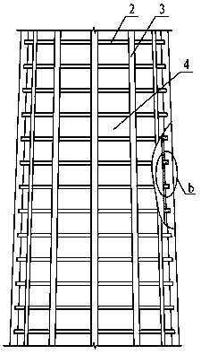
[0060] A frame thin-walled concrete chimney outer wall, which consists of: a chimney body 1, the upper part of the chimney body is connected to a top hoop 11, the chimney body includes a frame structure, and the frame structure includes a cast-in-place horizontal concrete beam 2 and the concrete columns 3 on the basis of the cast-in-place concrete beams 2, thin-walled curved prefabricated panels 4 are installed between the concrete columns 3, and the lower ends of the thin-walled curved prefabricated panels 4 are located On the horizontal concrete beam 2, the horizontal direction of the thin-walled curved prefabricated slab 4 is connected to the concrete column 3, or the thin-walled curved prefabricated slab 4 is horizontally connected to the The above-mentioned concrete column 3 is connected, and the upper end of the described thin-walled arc-shaped prefabricated plate 4 supports the above-mentioned concrete beam 2, and the described components support each other during the co...

Embodiment 2

[0062] For the outer wall of the frame thin-walled concrete chimney described in Embodiment 1, the thin-walled arc-shaped prefabricated slab 4 is connected by welding between embedded connectors 41, welded connections between embedded connectors 41 and transition pieces 42, or bolts The fixed connection with the concrete column 3 and / or the concrete beam 2 is realized by means of connection or adhesive connection, and the embedded connectors 41 are all force transmission connectors, and the connection mode of the embedded connectors is better than that of the existing steel bar insertion. The installation speed of pouring method is increased by more than 80%.

Embodiment 3

[0064] For the outer wall of the frame thin-walled concrete chimney described in embodiment 1 or 2, the concrete column 3 has a concrete column formwork connection hole 31, and the end of the thin-walled arc-shaped prefabricated plate 4 has a concrete beam formwork connection hole 47. When pouring concrete beams 4 and concrete columns 5 during on-site construction, the concrete beam formwork 49 and concrete column formwork 32 can be directly connected to the formwork connection holes; the thin-walled arc-shaped prefabricated slab 4 is distributed with reinforcement mesh 43. The steel mesh 43 protrudes from the thin-walled arc-shaped precast panel 4 at the upper end, and the lower end of the thin-walled arc-shaped precast panel 4 has a slurry groove 44, and the thin-walled arc-shaped precast panel 4 The side of the lower end of 4 has a grouting hole 45, and there are installation joints between the left and right ends of the thin-walled arc-shaped prefabricated panel 4 and the c...


PUM


Abstract

The invention discloses a framework thin wall type concrete chimney outer wall and a building method thereof. A bottom layer of a chimney in an existing mold overturning construction technology needsto completely achieve a corresponding hardening strength, then a wall body can be upwards built, lots of manual work and time are consumed during formwork erecting, and construction site management isnot facilitated due to small formwork accumulation. The framework thin wall type concrete chimney outer wall comprises a chimney body, and the upper portion of the chimney body is connected with a top hoop; the chimney body comprises a framework structure; the framework structure comprises cast-in-place horizontal concrete beams and concrete columns on bases of the cast-in-place concrete beams; thin wall arc-shaped prefabricated plates are installed between the concrete columns; the lower ends of the thin wall arc-shaped prefabricated plates are located on the horizontal concrete beams; the horizontal direction of the thin wall arc-shaped prefabricated plates is connected with the concrete columns, or the thin wall arc-shaped prefabricated plates are horizontally connected and then are connected with the concrete columns; the upper ends of the thin wall arc-shaped prefabricated plates are used for supporting the concrete beams on the upper portions; the curved faces of the thin wall arc-shaped prefabricated plates are part of the surface of a conical body; the concrete columns and the concrete beams jointly form a concrete net in a cone frustum shape; and the concrete net where the thin wall arc-shaped prefabricated plates are embedded forms the chimney outer wall. The framework thin wall type concrete chimney outer wall is used for chimney building.

Description

Technical field: [0001] The invention relates to a reinforced concrete chimney used in industry or power generation and drying equipment, in particular to a frame thin-walled concrete chimney and a construction method thereof. Background technique: [0002] A chimney is a ventilation structure for hot flue gas or smoke from a boiler, and it is also an exhaust tool for removing gas or smoke caused by fire. It is a towering structure that discharges smoke into the sky. It can improve the combustion conditions and reduce the pollution of flue gas to the environment. Chimneys are usually vertical, or as close to vertical as possible, to ensure a smooth flow of gases, drawing air into what is known as stack combustion or the stack effect. The space inside the chimney is called the flue. [0003] The height of a chimney affects its ability to transport flue gases to the outside environment through the stack effect. In addition, the use of chimneys for the dispersion of polluta...

Claims


Application Information

Patent Timeline
Patent Type & Authority Applications(China)
IPC IPC(8): E04H12/28E04H12/34
CPCE04H12/28E04H12/34
Inventor 刘旭刘全义
Owner 刘旭
Learn More