
Hydraulic hybrid four wheel drive

a hybrid four-wheel drive and hybrid technology, applied in the direction of braking systems, braking components, transportation and packaging, etc., can solve the problems of heavy transfer case, prone to wear, inability to engage in normal traction conditions, etc., and achieve the effect of improving engine braking

Inactive Publication Date: 2009-06-23
INT TRUCK INTPROP LLC
View PDF23 Cites 17 Cited by
  • Summary
  • Abstract
  • Description
  • Claims
  • Application Information

AI Technical Summary

Benefits of technology

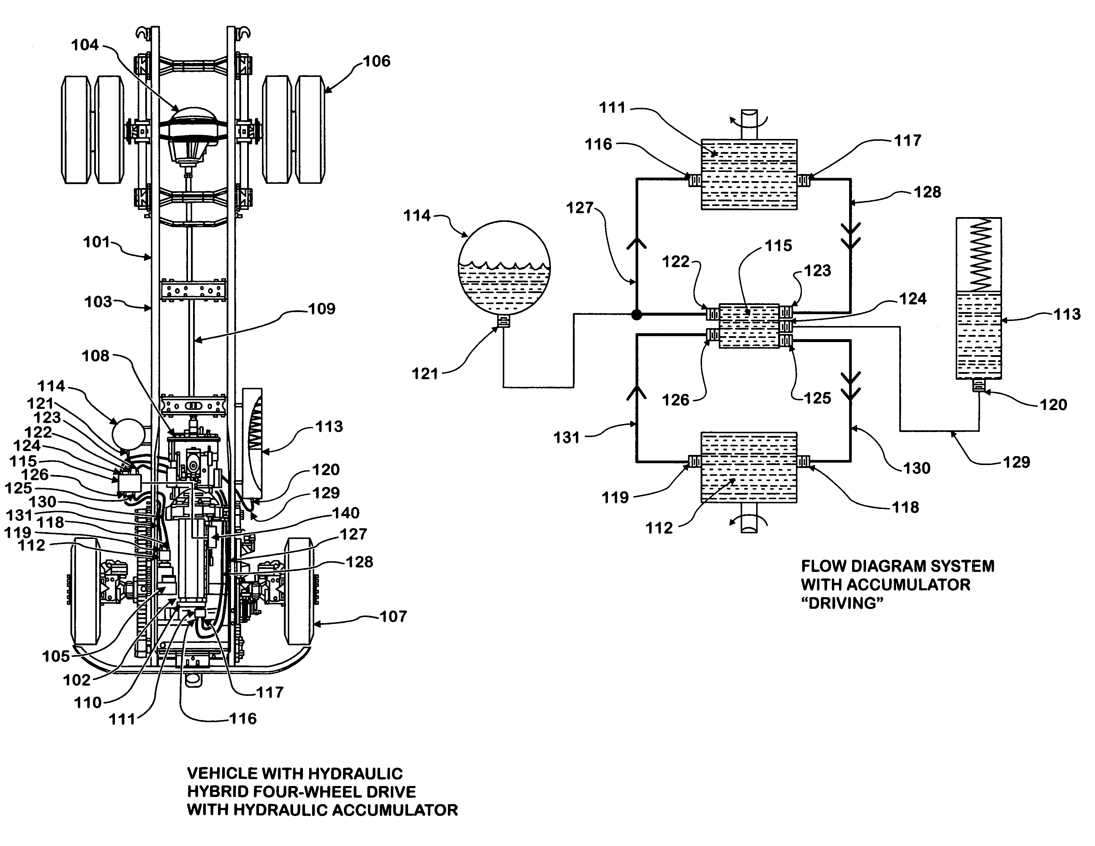
[0004]Currently, there is much prior art involving the use of hydraulic systems in vehicles to transmit power from the vehicle engine to the vehicle drive wheels. Many of these systems utilize an hydraulic pressure accumulator to store energy captured during vehicle braking. The presence of this hydraulic pressure accumulator in the prior art is due to a strong industry interest in increasing vehicle fuel efficiency, especially in conditions where the vehicle is required to start and stop repeatedly.
[0006]In either case, the vehicle retains its conventional rear axle or axles, and drivetrain. In this way hydraulic hybrid four wheel drive may be implemented using conventional hardware, requiring very little modification to the design of a given medium or heavy-duty vehicle, while eliminating the bulky transfer case and front propeller shaft of the typical four wheel drive configuration.
[0015]During the condition wherein both “braking” and “storing energy” are occurring, hydraulic pressure is directed both from the engine driven hydraulic pump and from the conventional front drive steering axle coupled hydraulic motor to the hydraulic pressure accumulator. Makeup volume to replace the fluid pumped into the hydraulic pressure accumulator is provided by the hydraulic reservoir. This condition occurs when the conventional front drive steering axle is being used to help slow the vehicle, and when it is desired to store energy being produced by the vehicle engine as potential energy in the hydraulic pressure accumulator for later use in propelling the vehicle. The power consumed by the engine driven hydraulic pump may assist in engine braking through the conventional drivetrain.
[0016]In the case of a system configured without an hydraulic pressure accumulator, among the aforementioned conditions, only “driving” may be accomplished. Some braking effect may be accomplished by controlling the displacement of the variable displacement engine driven pump, thereby transferring power back to the conventional drivetrain in order to enhance engine braking.

Problems solved by technology

There are several significant drawbacks to the typical four wheel drive configuration for medium and heavy-duty vehicles.
The transfer case is heavy and consumes power, even when four wheel drive is not in use.
It is prone to wear, and cannot be engaged during normal traction conditions, due to binding caused by rotational differential between front and rear axles.

Method used


Image

  • Hydraulic hybrid four wheel drive
  • Hydraulic hybrid four wheel drive
  • Hydraulic hybrid four wheel drive

Examples


Embodiment Construction

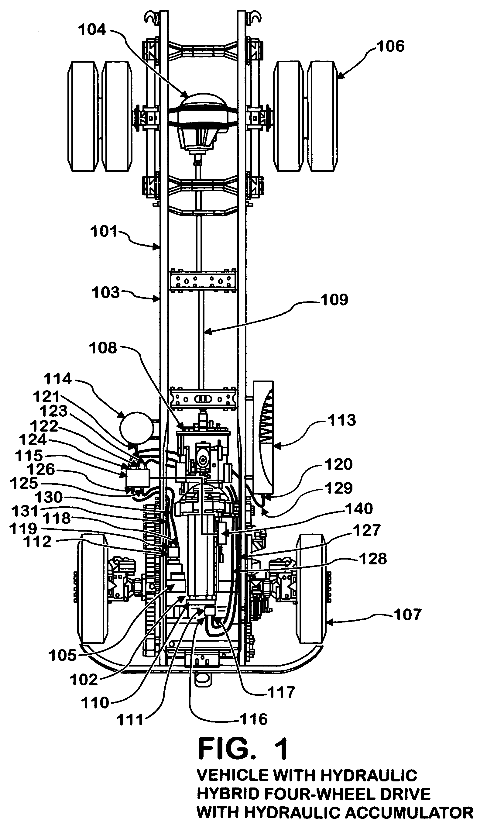
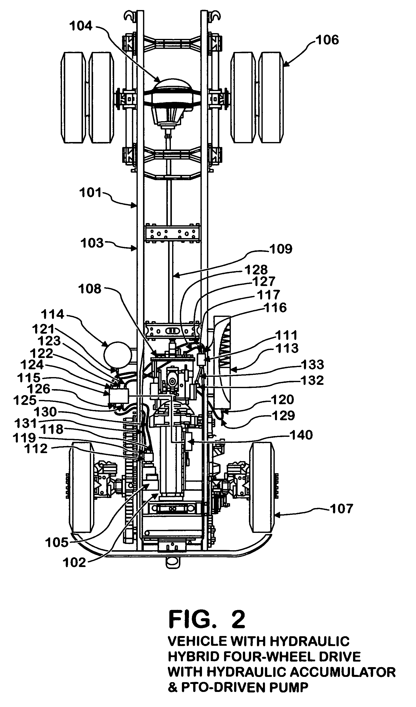
[0033]The vehicle 101 shown in FIG. 1 has an engine 102 attached to a chassis 103. The vehicle 101 also has at least one rear axle 104 and one conventional front drive steering axle 105 attached to chassis 103. The rear axle 104 is provided with rear wheel and tire assemblies 106, and the conventional front drive steering axle 105 is provided with front wheel and tire assemblies 107. The engine 102 provides power to a transmission 108, which in turn provides power to a propeller shaft 109. The propeller shaft 109 thereby provides power to rear axle 104 and to rear wheel and tire assemblies 106.

[0034]The engine 102 shown in FIG. 1 is provided with a Front Engine Accessory Drive (FEAD) 110, which provides power to an hydraulic pump 111 attached to it. The conventional front drive steering axle 105 is provided with an hydraulic motor 112. The chassis 103 is further provided with an hydraulic pressure accumulator 113, an hydraulic reservoir 114, a control valve 115, and a control means ...


PUM


Abstract

An hybrid four wheel drive system characterized by a vehicle having a conventional rear wheel driveline as well as a conventional driving front steer axle powered by an hydraulic motor. The hybrid four wheel drive system is provided in multiple embodiments, particularly with and without an hydraulic pressure accumulator.

Description

BACKGROUND OF INVENTION[0001]This invention relates to a vehicle equipped with an hybrid four wheel drive system that is simpler to install than conventional four wheel drive systems, and may allow partial regenerative braking, depending on the configuration of the invention. Specifically, multiple embodiments are disclosed, all of which are characterized by a vehicle having a conventional rear wheel driveline as well as a conventional driving front axle. In lieu of a transfer case and front propeller shaft, as is often used in four wheel drive vehicles, the front axle is powered by an hydraulic motor. Pressurized hydraulic fluid is provided by an hydraulic pump driven by the vehicle main engine.SUMMARY[0002]Mobile vehicles, especially medium and heavy-duty commercial vehicles, are commonly configured with the engine located longitudinally forward of the cab and mounted to a set of frame rails, which form the structure of the vehicle. The engine is coupled to a transmission, which i...

Claims


Application Information

Patent Timeline
Patent Type & Authority Patents(United States)
IPC IPC(8): B60K17/356
CPCB60K6/12B60K6/52B60K17/356B60W10/04B60W20/00B60Y2200/14Y02T10/62
Inventor DELANEY, PATRICK M.
Owner INT TRUCK INTPROP LLC
Learn More