Semiconductor device
a technology of semiconductor devices and semiconductors, applied in semiconductor devices, semiconductor/solid-state device details, electrical apparatus, etc., can solve problems such as cracks in the dicing region, and achieve the effect of effectively preventing the noise transmission between the first device region and the second device region, reducing the total capacity c, and increasing the impedance z suitably
- Summary
- Abstract
- Description
- Claims
- Application Information
AI Technical Summary
Benefits of technology
Problems solved by technology
Method used
Image
Examples
embodiment 1
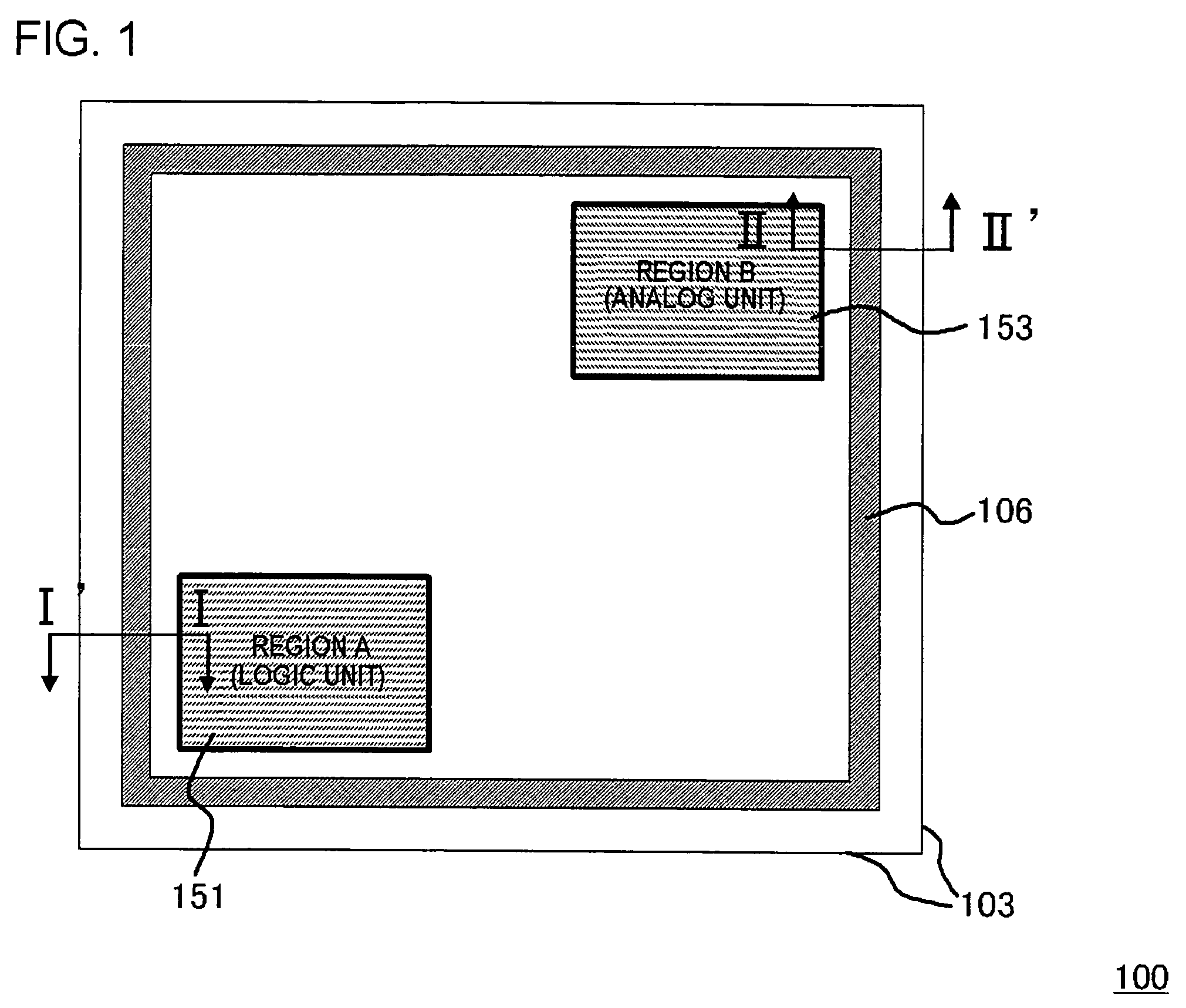
[0048]FIG. 1 is a plan view showing a configuration of a semiconductor chip in this embodiment. A semiconductor chip 100 shown in FIG. 1 includes two device regions, that is, a logic unit 151 (region A) and an analog unit 153 (region B) in a silicon substrate 101. The semiconductor chip 100 includes a annular seal ring region 106 surrounding these device regions along a dicing plane 103. There will be described an exemplary configuration where a seal ring 105 (FIGS. 2 and 3) formed in the seal ring region 106 is comprised of a triple-layered annular conductive plug.
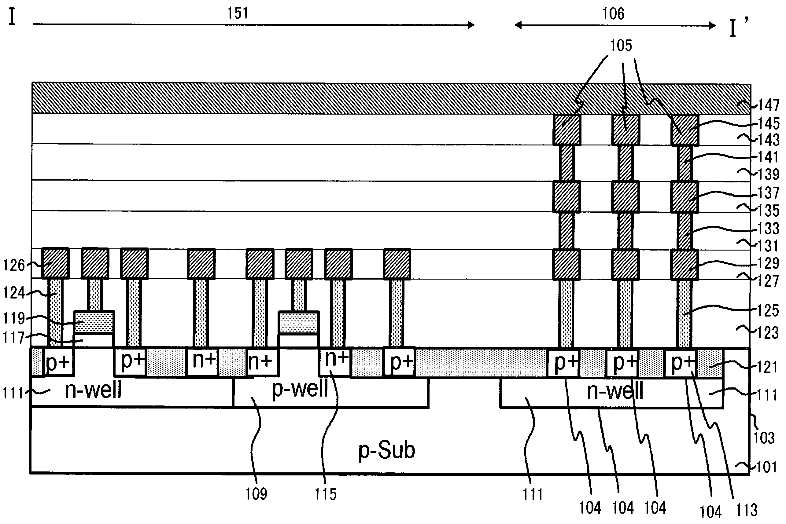
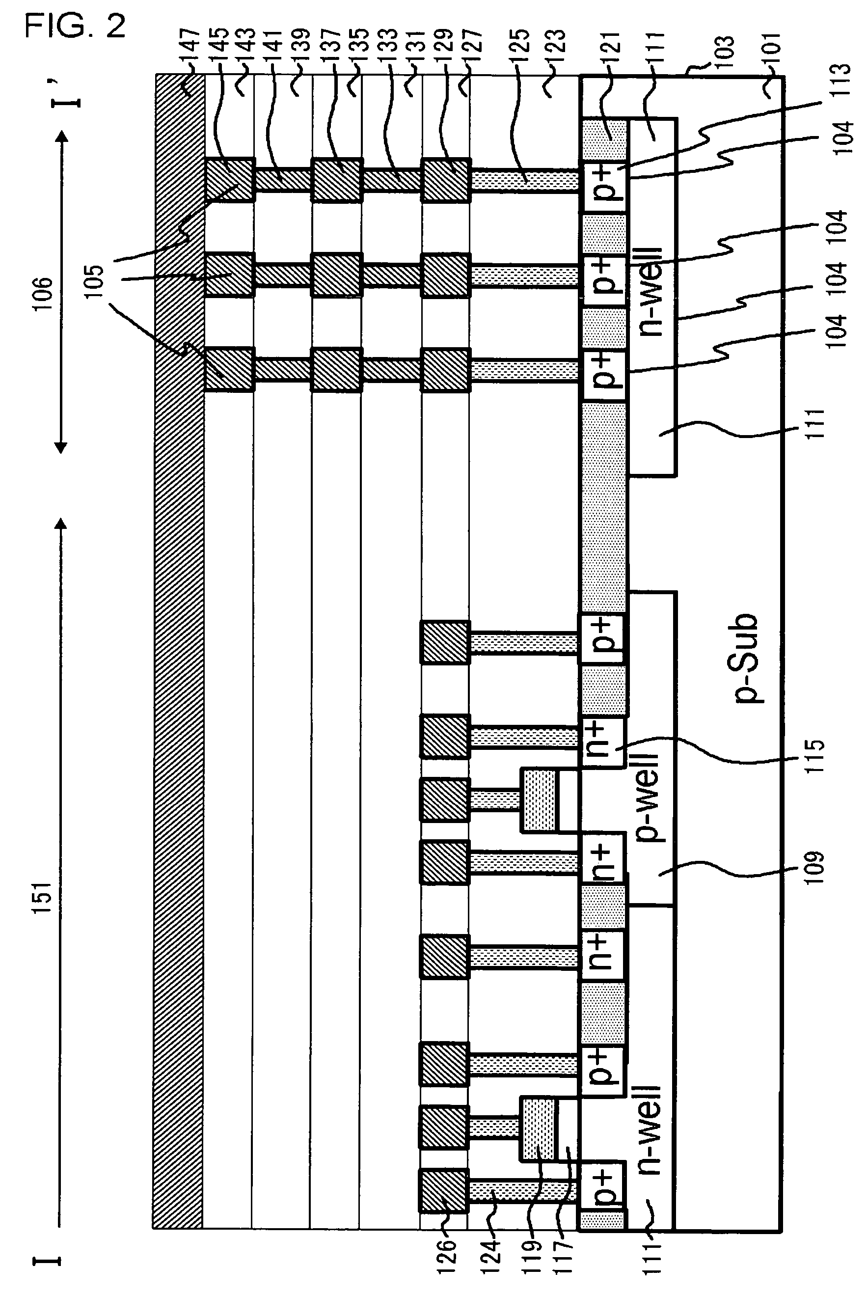
[0049]FIG. 2 is a cross-sectional view taken on line I-I′ of FIG. 1, and FIG. 3 is a cross-sectional view taken on line II-II′ of FIG. 1. Each of FIGS. 2 and 3 shows a configuration of the seal ring region 106 and an internal circuit adjacent to the region.
[0050]The semiconductor chip 100 shown in FIGS. 1 to 3 is a semiconductor device comprising the first and the second device regions (the logic unit 151 and the analog u...
embodiment 2
[0093]In the semiconductor chip described in Embodiment 1, the seal ring region 106 may have the following cross-sectional structure. In this embodiment, a planar configuration in the semiconductor chip may be also as described with reference to FIG. 1. FIG. 4 is a cross-sectional view showing a configuration of the semiconductor device according to this embodiment. Although FIG. 4 shows a cross-sectional view taken on line II-II′ of FIG. 1 which corresponds to FIG. 3 in Embodiment 1, the I-I′ cross-section may have the configuration in FIG. 4, in which the analog unit 153 in FIG. 4 is the logic unit 151.
[0094]As shown in FIG. 4, the semiconductor device of this embodiment includes a diffusion layer (an n+-diffusion layer 115 and an n-well 111) with an opposite conductivity type to that of a silicon substrate 101 near the surface of the silicon substrate, and a seal ring 105 is connected to the surface of the n+-diffusion layer 115. Furthermore, a junction plane in the n-well 111 is...
embodiment 3
[0102]In the semiconductor chip described in Embodiment 1, the seal ring region 106 may have the following cross-sectional configuration. Again, in this embodiment, a planar configuration of the semiconductor chip is as described with reference to FIG. 1. FIG. 5 is a cross-sectional view showing the configuration of the semiconductor device according to this embodiment. Although FIG. 5 shows a cross-sectional view taken on line II-II′ of FIG. 1 which corresponds to FIG. 3 in Embodiment 1, the I-I′ cross-section may have the configuration in FIG. 5, in which the analog unit 153 in FIG. 5 is the logic unit 151.
[0103]As shown in FIG. 5, in the semiconductor device of this embodiment, seal ring region 106 has a basic configuration as described for the semiconductor chip in Embodiment 2, except that an n-well 111 is not formed in a silicon substrate 101.
[0104]Again, in this embodiment, the bottom of the seal ring 105, that is, the bottom of the first conductive ring 125 is in contact wit...
PUM
 Abstract
Description
Claims
Application Information
 - R&D
- Intellectual Property
- Life Sciences
- Materials
- Tech Scout
- Unparalleled Data Quality
- Higher Quality Content
- 60% Fewer Hallucinations
Browse by: Latest US Patents, China's latest patents, Technical Efficacy Thesaurus, Application Domain, Technology Topic, Popular Technical Reports.
© 2025 PatSnap. All rights reserved.Legal|Privacy policy|Modern Slavery Act Transparency Statement|Sitemap|About US| Contact US: help@patsnap.com


