
Circuit and Method for Providing Access to a Test and/or Monitoring System

a monitoring system and circuit technology, applied in the direction of electric digital data processing, supervising/monitoring/testing arrangements, instruments, etc., can solve problems such as deteriorating the transmission quality of lines, and achieve the effect of accurate measuremen

Inactive Publication Date: 2007-12-06
CORNING RES & DEV CORP
View PDF9 Cites 0 Cited by
  • Summary
  • Abstract
  • Description
  • Claims
  • Application Information

AI Technical Summary

Benefits of technology

[0004] The invention provides a circuit for providing test and / or monitoring access to at least two telecommunication lines, which is improved with regard to the accuracy of measurements and / or the opportunities offered by the circuit with regard to the types of telecommunication lines, which can be tested or measured by such a circuit. In particular, also telecommunication lines, which transmit signals at high frequencies, can be accurately measured.
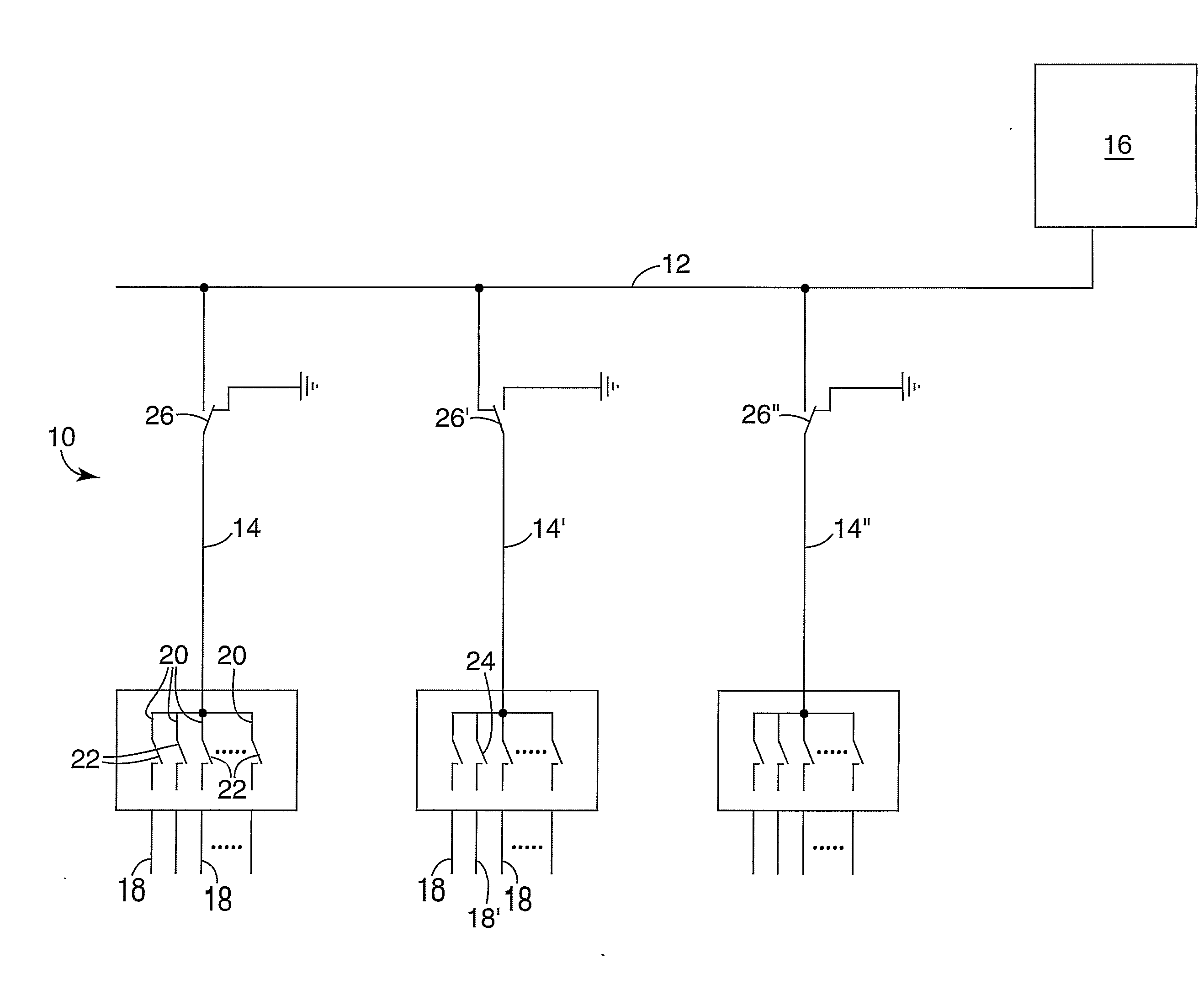
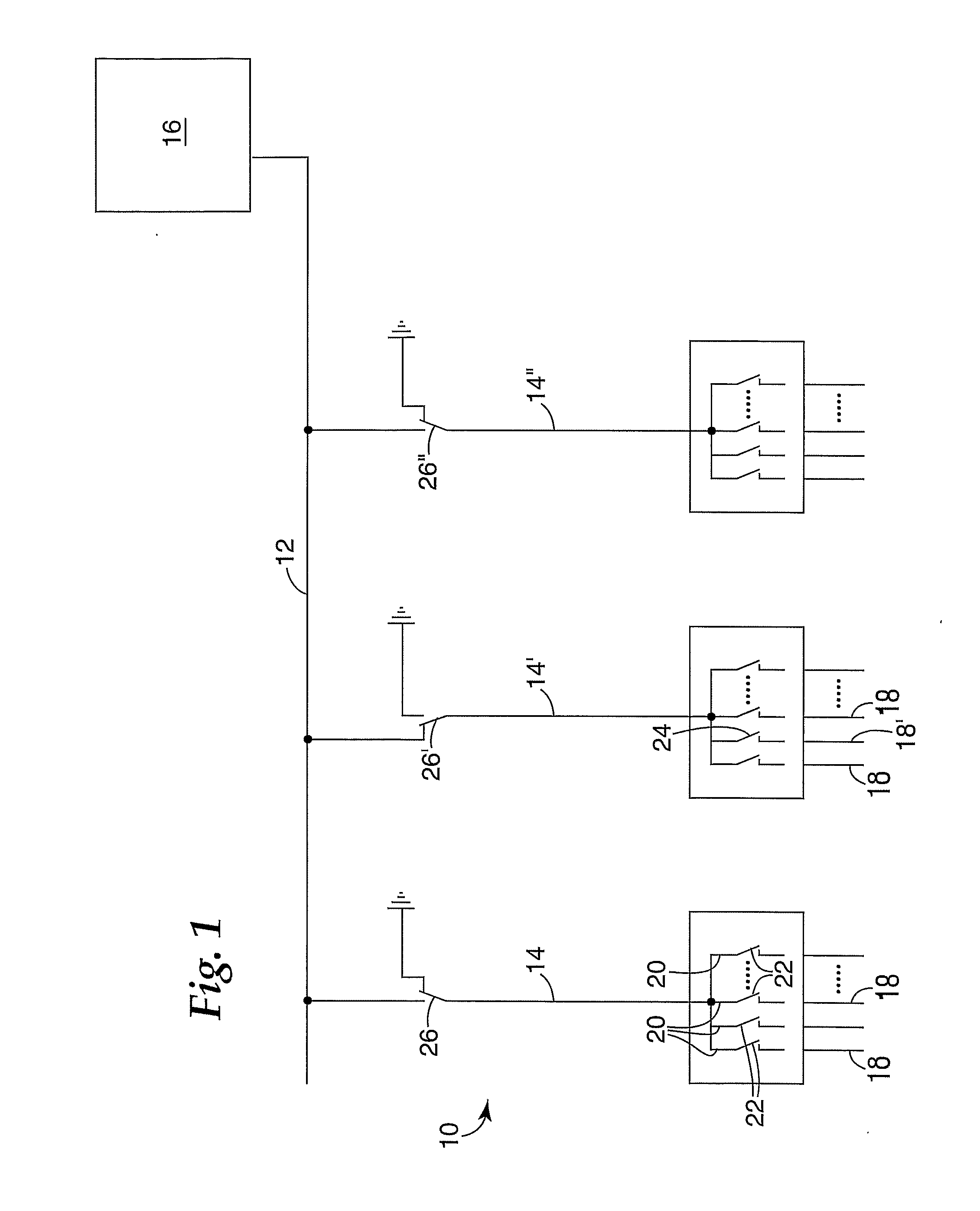
[0007] In the circuit at least one of the primary branches is provided with at least one switch, which, in a first state, connects the primary branch with the bus and, in a second state, connects the primary branch with ground. The switch does not necessarily have to “belong to” the primary branch. Rather, it is sufficient when the switch is provided at the connection between the primary branch and the bus in any suitable manner to provide the above-mentioned, at least two states. In this context, ground could also be called signal ground and essentially has the following effects. Each primary branch that remains connected with the bus while it is not in use, i.e. while the telecommunication line connected therewith is not accessed, adds to the capacitive load on the bus. This creates a parasitic capacitance. This effect is particularly relevant for primary branches which have secondary branches and switches connecting the secondary branches with the primary branch. These contribute to the parasitic capacitance and deteriorate the transmission quality of the line. In other words, the signal, which is obtained from the test and monitoring line involving the bus and the primary branches, is improved by the novel circuit described herein. In particular, noise from any primary branches which are momentarily not in use is prevented, to a highly relevant extent, from being transferred to the bus. Thus, precise measurements, in order to test and / or monitor a particular telecommunication line, can be conducted by the bus and that primary branch of the circuit, which is momentarily in use.
[0009] This is to a certain extent realized in the present invention by the fact that all those primary branches which are momentarily not in use, are connected with ground. By disconnecting those primary branches, their capacitances can be taken away from the bus. However, the disconnected primary branches can still act like antennae and can thus transmit signals to adjacent primary branches. Since one adjacent primary branch would be momentarily in use, the described effect has the potential to deteriorate the measurement, which is made via the momentarily used primary branch. However, connecting primary branches, which are momentarily not in use, with signal ground, will drain any current which might have been induced, and thus, substantially prevents the transmission of noise to adjacent primary branches. In summary, the circuit described herein has at least one additional multiplex level allowing a particular primary branch to be connected with the bus and the remaining primary branches to be disconnected from the bus in order to achieve the above-described effects. While these effects can be obtained by enabling a single primary branch to be connected with ground when it is not in use, the described effects are particularly strong when all those primary branches that are momentarily not in use, are disconnected from the bus and grounded. In particular, the disconnected state can constitute an initial or “normal state”, wherein only that primary branch, through which test and / or monitoring measurements are to be conducted, is connected with the bus. All remaining primary branches can remain connected with ground. The connection of “unused” primary branches with ground does not necessarily have to be continuous. In other words, the unused primary branches can be connected with ground only at certain times, for example, only when measurements are made via certain primary branches. The “unused” primary branches, which may have been disconnected from the bus before, can, at the time of measurement, be connected with ground in order to improve the accuracy of the measurements as described above.
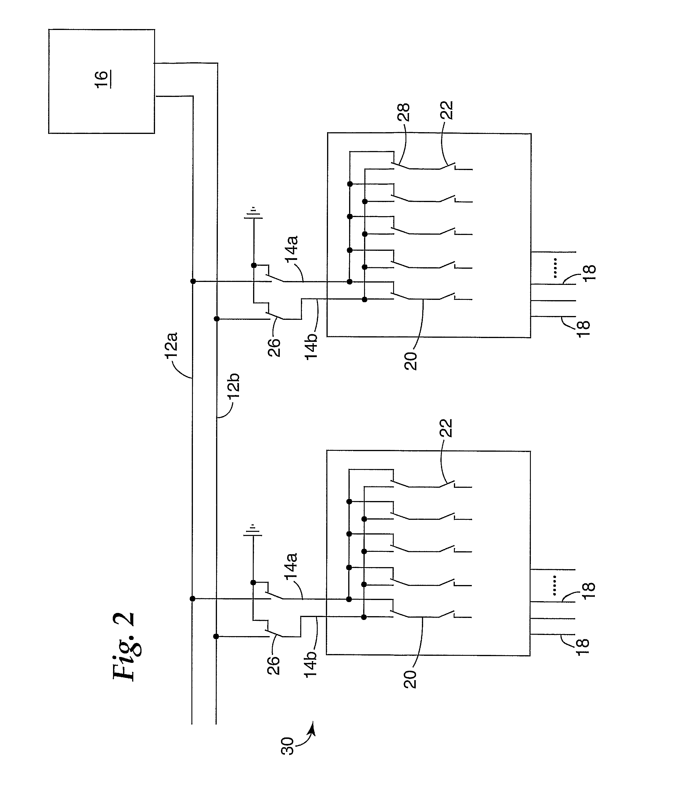
[0011] In certain applications at least two buses can be provided, and at least one primary branch can comprise at least two sub-branches, each of the sub-branches being connected with one of the buses. At least one further switch can be provided which allows a telecommunication line to be tested with either one of the buses. Such a switch has the particular advantage of allowing tests and measurements to be made via a selected one of the buses and sub-branches. However, such a switch particularly contributes to the parasitic capacitance and coupling between the sub-branches. Therefore, the possibility of connecting an unused primary branch, in particular its sub-branches with ground, is particularly advantageous.

Problems solved by technology

These contribute to the parasitic capacitance and deteriorate the transmission quality of the line.

Method used


Image

  • Circuit and Method for Providing Access to a Test and/or Monitoring System
  • Circuit and Method for Providing Access to a Test and/or Monitoring System
  • Circuit and Method for Providing Access to a Test and/or Monitoring System

Examples


Embodiment Construction

[0022] In FIG. 1, a circuit 10 generally consists of a bus 12 and several (in the case shown three) primary branches 14, 14′, 14″. The bus 12 is connected with a measuring device 16, which is provided to allow test of those telecommunication lines (described below), which are to be tested and / or monitored. Reference number 18 denotes the telecommunication lines. As is apparent from FIG. 1, several telecommunication lines 18 are grouped together, with three groups being shown in FIG. 1. This schematically indicates that several telecommunication lines are, as will be apparent to those skilled in the art, connected with contacts of a particular terminal module. Thus, as indicated in the drawing, one primary branch 14 can be connected with secondary branches 20 as described below, which are in turn connected with the telecommunication lines of a particular module. Thus, it can be said that each primary branch 14, 14′, 14″ is associated with a particular terminal module. However, this m...


PUM


Abstract

A circuit (10) and method for providing test and / or monitoring access to at least two telecommunication lines (18). This circuit (10) comprises at least one bus (12) and at least two primary branches (14) extending there from, at least one of the primary branches (14) being provided with at least one switch (26), which in a first state connects the primary branch (14) with the bus (12) and in a second state connects the primary branch (14) with ground. The method comprises the step of connecting only that primary branch (14), through which access to a telecommunication line 18 is to be established, with the bus (12).

Description

TECHNICAL FIELD [0001] The invention relates to a circuit and a method for providing test and / or monitoring access to at least two telecommunication lines. BACKGROUND [0002] In the field of telecommunications numerous customers are connected with the switch or other equipment like line terminating equipment or multiplex systems (e.g. a Digital Subscriber Line Access Multiplex, DSLAM) of a telecommunications company via telecommunication lines. Between the customer and the switch or other equipment sections of the telecommunication lines are connected with connection points, such as terminal modules. The terminal modules establish an electrical connection between a wire, which is connected to the terminal module at a first side, and another wire, which is connected to the terminal module at a second side. There is sometimes a need to carry out measurements for the connection thus established. Measurements can be made, for example, between the telephone connection of a customer and th...

Claims


Application Information

Patent Timeline
IPC IPC(8): G06F13/20H04M3/22H04M3/30H04Q1/14
CPCH04M3/22H04Q1/20H04M3/305H04M3/30
Inventor PFANNKUCHEN, RALF
Owner CORNING RES & DEV CORP
Learn More