L-type distribution structure of converter transformer in valve hall of UHV DC converter station

A converter transformer and UHV DC technology, applied in the field of electric power buildings, can solve the problems of large occupation area of ​​the converter station, difficult steering, long time, etc., to reduce the initial investment cost, realize common rail transportation, and cover small effect

Active Publication Date: 2018-01-26
CHINA ENERGY ENG GRP GUANGDONG ELECTRIC POWER DESIGN INST CO LTD
View PDF5 Cites 0 Cited by
  • Summary
  • Abstract
  • Description
  • Claims
  • Application Information

AI Technical Summary

Problems solved by technology

[0004] The purpose of the present invention is to provide a UHV DC converter station valve to solve the problems of large occupied area of ​​existing face-to-face converter stations, difficulty in steering and long time when replacing spare high-end and low-end converter transformers, etc. Hall converter transformer L-shaped distribution structure

Method used


Image

  • L-type distribution structure of converter transformer in valve hall of UHV DC converter station

Examples


specific Embodiment 1

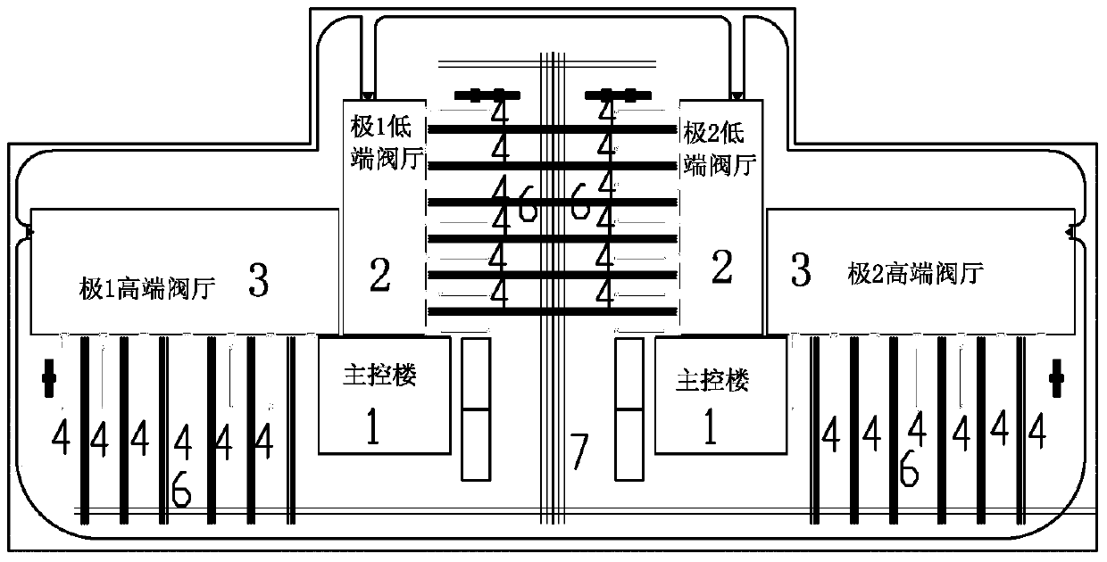
[0024] refer to figure 1 , this embodiment includes two main control buildings 1, two low-end valve halls 2, two high-end valve halls 3 and several converter transformers 4, the main control building 1, low-end valve halls 2, high-end valve halls 3 and the converter transformer 4 are arranged in left and right mirror images, wherein, the low-end valve hall 2 and the high-end valve hall 3 are arranged behind the main control building 1 in an L-shaped distribution, and the low-end valve hall 2 is longitudinally distributed in the main control building 1, the high-end valve hall 3 is laterally distributed on the outside of the low-end valve hall 2; a part of the converter transformer 4 is distributed on the inner side of the low-end valve hall 2 in a horizontal "one" arrangement, and the converter transformer 4 The other part is distributed in the front side of the high-end valve hall 3 in a vertical arrangement of "one"; the access wire of the converter transformer 4 is directly...


PUM


Abstract

The invention relates to an L-shaped distribution structure of a converter transformer in a valve hall of an UHV DC converter station, including two main control buildings, two low-end valve halls, two high-end valve halls and several converter transformers. The end valve halls, high-end valve halls and converter transformers are arranged in left and right mirror images, among which, the low-end valve halls and high-end valve halls are located behind the main control building in an L-shaped distribution, and the low-end valve halls are longitudinally distributed in the main On the back side of the building, the high-end valve hall is distributed horizontally outside the low-end valve hall; a part of the converter transformer is distributed inside the low-end valve hall in a horizontal "one" arrangement, and the other part of the converter transformer is distributed in the high-end valve hall. The front side is arranged in a vertical "one" shape; the access wires of the converter transformer are directly inserted into the terminals of the low-end valve hall and the high-end valve hall through the DC wall bushing, and the output of the converter transformer is converged through the high-span wires to form a Double "L"-shaped distribution structure symmetrically distributed on both sides of the high-span conductor. The invention has flexible and compact layout, small occupied area, and can reduce cost.

Description

technical field [0001] The invention relates to an L-shaped distribution structure of a valve hall converter transformer of an UHV DC converter station, which can be applied to double valves and single-phase double-winding converter transformer equipment in power plants, and is especially suitable for ±800kV UHV DC converter stations Arrangement structure of valve hall converter transformer. It belongs to the field of electric construction. Background technique [0002] With the development of my country's economy and the implementation of long-distance large-capacity power transmission projects such as west-to-east power transmission, there are more and more ±800kV UHV DC power transmission projects. The converter stations at the sending and receiving ends adopt the connection mode of two sets of 12-pulse converter valves connected in series for each pole, that is, four valve halls need to be set up for both poles of each converter station. The UHV converter station occup...

Claims


Application Information

Patent Timeline
Patent Type & Authority Patents(China)
IPC IPC(8): H02B7/06
Inventor 孔志达李扶中周敏韦文兵林刚张军王建武廖毅
Owner CHINA ENERGY ENG GRP GUANGDONG ELECTRIC POWER DESIGN INST CO LTD
Why Eureka
Try Eureka