Magnetic resonance apparatus, method and auxilliary coil element for manipulation of the B1 field

a magnetic resonance and auxilliary coil technology, applied in the direction of instruments, magnetic measurements, measurement devices, etc., can solve the problems of poor exposure, poor exposure, and poor reliability of magnetic resonance measurement in specific areas

Inactive Publication Date: 2009-06-23
SIEMENS HEALTHCARE GMBH
View PDF5 Cites 8 Cited by
  • Summary
  • Abstract
  • Description
  • Claims
  • Application Information

AI Technical Summary

Benefits of technology

[0012]A specific region can thus be influenced with the inventive method without a dielectric cushion or another field correction element having to be placed at this region itself, whereby the aforementioned disadvantages are avoided.
[0021]The use of such an actively connected auxiliary coil element has the advantage that the auxiliary coil element can also be wired such that it is activated only during the adjustment measurement and is permanently deactivated during the actual magnetic resonance measurement insofar as this is desired in the individual case.

Problems solved by technology

In individual cases this can lead to the situation that a reliable magnetic resonance measurement is problematic in specific body regions of the patient and delivers unusable results.
A typical problem case is the region of the spinal column of the patient.
An acquisition of the spinal column image data without field correction would therefore lead to a poor exposure and to a lower signal / noise ratio, i.e. to a poorer contrast.
It is therefore disadvantageous to place dielectric cushions in the region of the spinal column (i.e. between the local coil and the back of the patient) since the distance between coil and patient is thereby increased.

Method used


Image

  • Magnetic resonance apparatus, method and auxilliary coil element for manipulation of the B1 field
  • Magnetic resonance apparatus, method and auxilliary coil element for manipulation of the B1 field
  • Magnetic resonance apparatus, method and auxilliary coil element for manipulation of the B1 field

Examples


Embodiment Construction

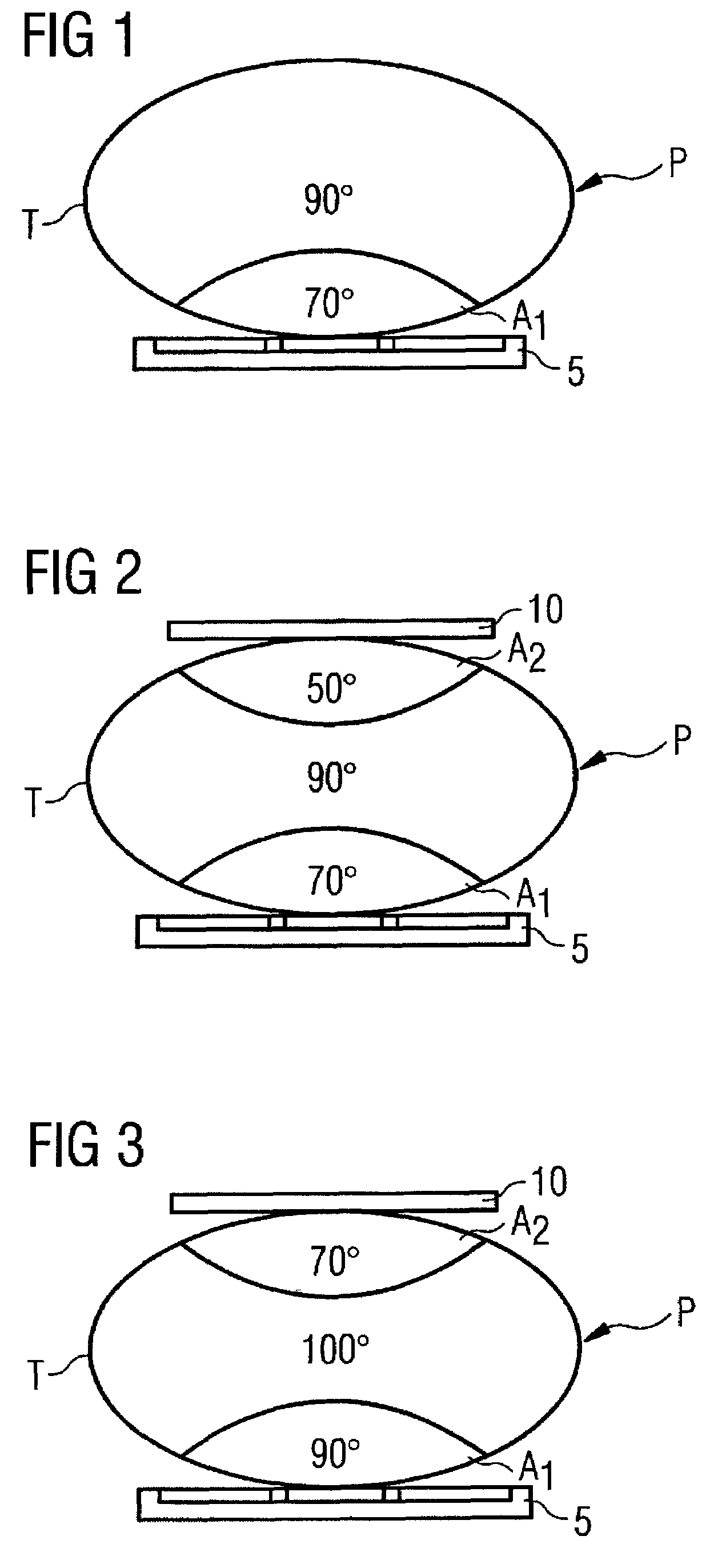
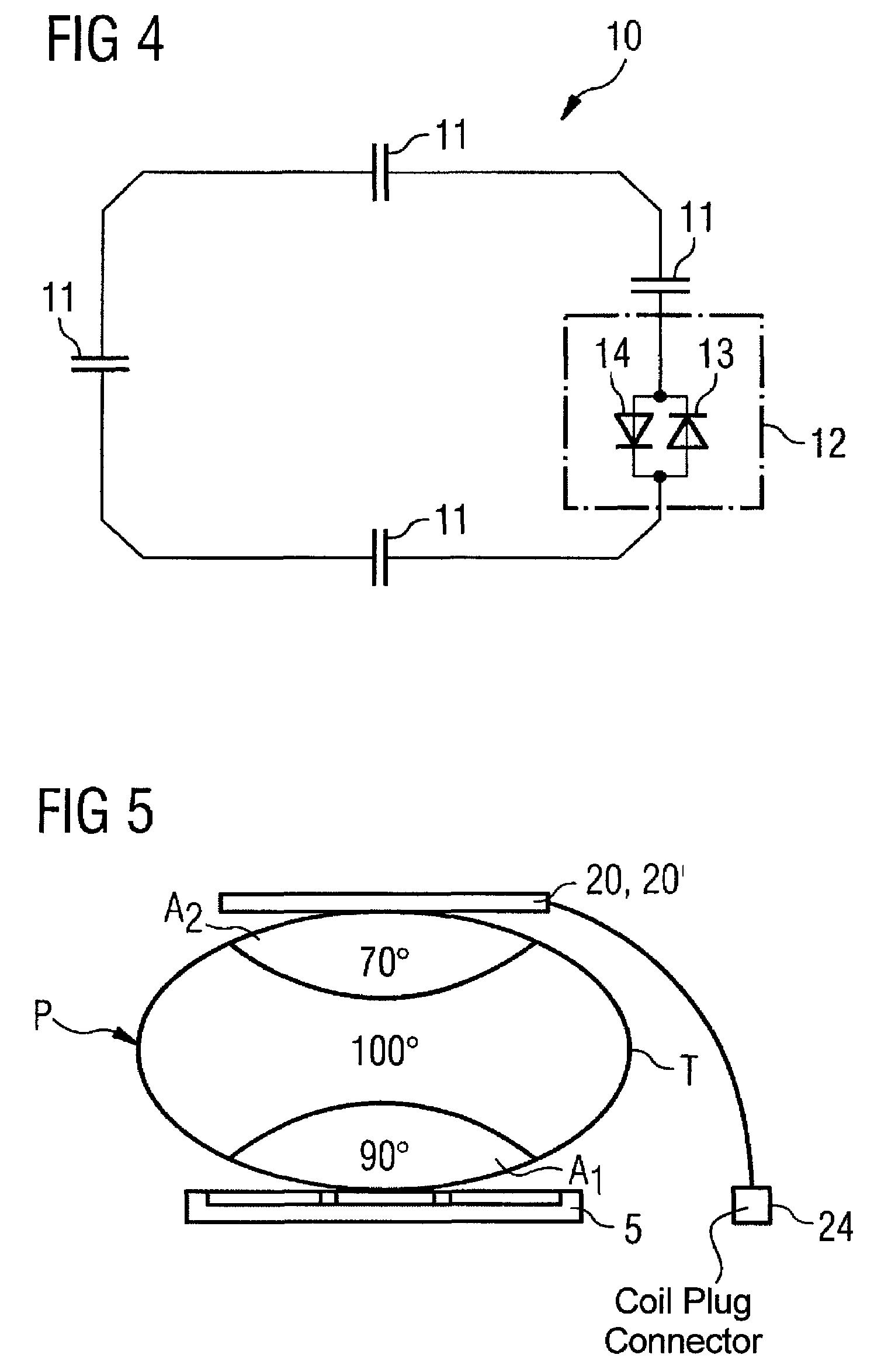
[0032]In the following the method is explained in a typical exemplary embodiment in which a magnetic resonance exposure of the spinal column region of a patient P should be generated. FIG. 1 shows such a typical exemplary embodiment. The patient P here lies with his or her back on a spinal column local coil 5. In the adjustment measurement a B1 field is set within a sub-volume T (here a relatively thick slice situated (i.e. lying in the image plane) perpendicular to the longitudinal axis of the patient) of the patient P such that an average flip angle of 90° is advantageously achieved in this sub-volume T.

[0033]The adjustment measurement ensues by emitting a specific radio-frequency field, then the flip angle distribution in the sub-volume T is measured and it is thus checked whether the radio-frequency field strength is sufficient or too low or too high. An adjustment of the transmission parameters then ensues so that the average flip angle of 90° is achieved with optimal precision...


PUM


Abstract

In a method and arrangement for local manipulation of a B1 field in a first region of an examination subject in an examination volume of a magnetic resonance system, a B1 measurement value that represents the B1 field in the sub-volume during an adjustment measurement is integrally determined, and in desired radio-frequency signal parameters for a subsequent magnetic resonance measurement are predetermined on the basis of the determined B1 measurement value. At least during the adjustment measurement, the B1 field is influenced within a second region counter to the manipulation intended in the first region by means of an auxiliary coil element which is arranged in or at the second region of the sub-volume remote from the first region.

Description

BACKGROUND OF THE INVENTION[0001]1. Field of the Invention[0002]The invention concerns a method for local manipulation of a B1 field in a first region of an examination subject arranged in an examination volume of a magnetic resonance system, and in which, in a calibration measurement, a B1 measurement value, that represents the average B1 field generated by an antenna arrangement of the magnetic resonance system, is integrally determined over at least one specific sub-volume of the examination volume (for example over a defined slice), and in which desired radio-frequency signal parameters (in particular an amplitude of the emitted radio-frequency signals) are predetermined for a subsequent magnetic resonance measurement on the basis of the determined B1 measurement value. The invention also concerns a magnetic resonance system as well as an auxiliary coil element for implementation of such a method.[0003]2. Description of the Prior Art[0004]Magnetic resonance tomography is a wide-...

Claims


Application Information

Patent Timeline
Patent Type & Authority Patents(United States)
IPC IPC(8): G01V3/00
CPCG01R33/341G01R33/3642G01R33/583G01R33/246G01R33/3664G01R33/422G01R33/5612G01R33/5659
Inventor GREIM, HELMUTWOLF, STEFFEN
Owner SIEMENS HEALTHCARE GMBH
Why Eureka
Try Eureka