Multifunction X-ray analysis system

a multi-functional, x-ray technology, applied in the direction of material analysis using radiation diffraction, instruments, measurement devices, etc., can solve the problems of the inability to perform both types of measurements using a single system, and achieve the effect of improving the accuracy and reliability of the system

Active Publication Date: 2009-06-23
BRUKER TECH LTD
View PDF67 Cites 116 Cited by
  • Summary
  • Abstract
  • Description
  • Claims
  • Application Information

AI Technical Summary

Problems solved by technology

Although XRR and SAXS are complementary in terms of the information they provide, there are difficulties inherent in performing both types of measurements using a single system.

Method used


Image

  • Multifunction X-ray analysis system
  • Multifunction X-ray analysis system
  • Multifunction X-ray analysis system

Examples


Embodiment Construction

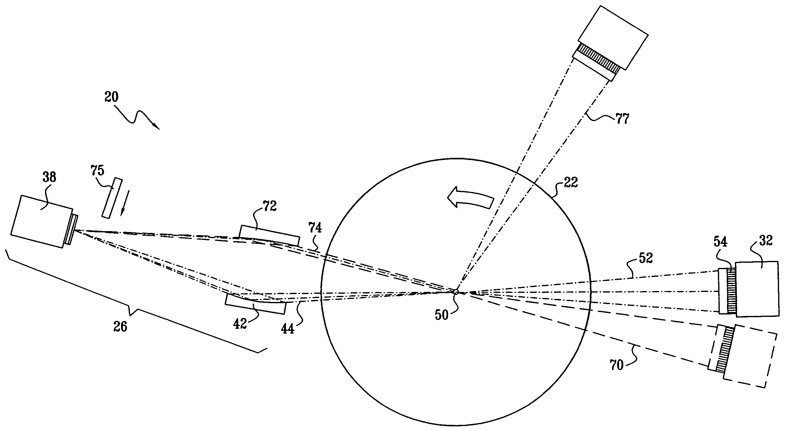
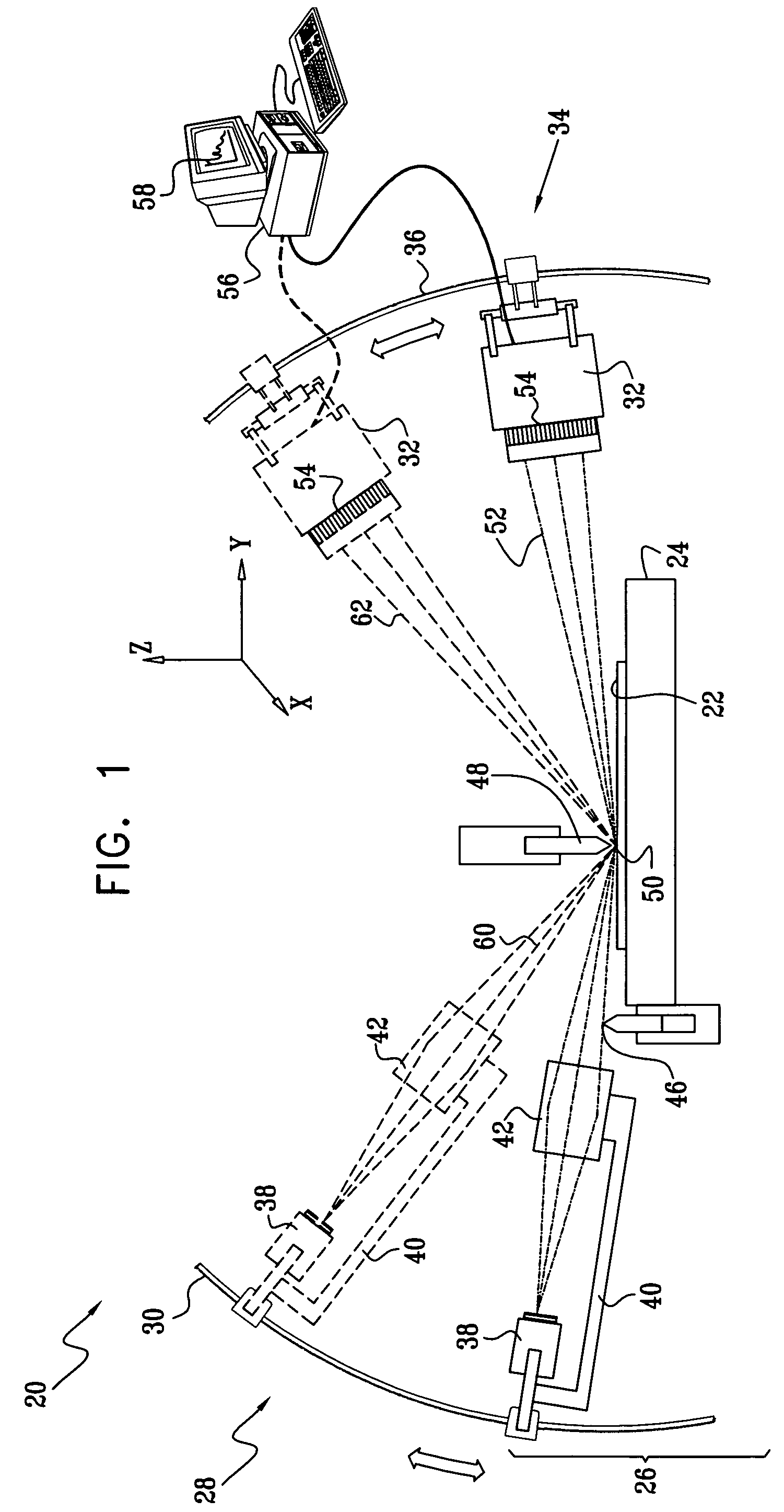
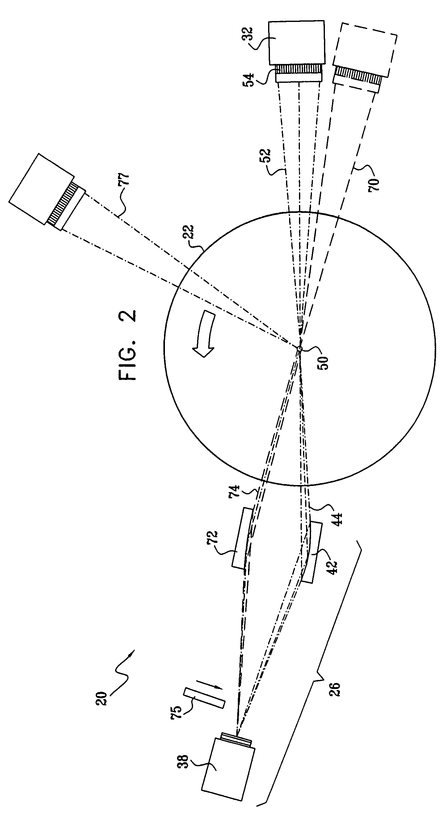
[0072]FIG. 1 is a schematic side view of a system 20 for measurement and analysis of X-ray scattering from a sample 22, in accordance with an embodiment of the present invention. System 20 is capable of performing X-ray reflectometry (XRR), small-angle X-ray scattering (SAXS) and X-ray diffractometry (XRD), in both high- and low-resolution modes. Sample 22 is mounted on a mounting assembly, such as a motion stage 24, allowing accurate adjustment of the position and orientation of the sample. An X-ray source 26 irradiates a small area 50 on sample 22. X-rays scattered from the sample are collected by a detector assembly 32.

[0073]A source motion assembly 28 shifts source 26 between upper and lower source positions for different types of measurements, as described hereinbelow. Similarly, a detector motion assembly 34 moves detector assembly 32 between upper and lower detector positions. The lower positions of the source and detector assemblies are typically used for XRR, SAXS, and opti...


PUM

PropertyMeasurementUnit
energyaaaaaaaaaa
incident anglesaaaaaaaaaa
elevation angleaaaaaaaaaa

Abstract

Apparatus for analysis of a sample includes a radiation source, which is adapted to direct a first, converging beam of X-rays toward a surface of the sample and to direct a second, collimated beam of the X-rays toward the surface of the sample. A motion assembly moves the radiation source between a first source position, in which the X-rays are directed toward the surface of the sample at a grazing angle, and a second source position, in which the X-rays are directed toward the surface in a vicinity of a Bragg angle of the sample. A detector assembly senses the X-rays scattered from the sample as a function of angle while the radiation source is in either of the first and second source configurations and in either of the first and second source positions. A signal processor receives and processes output signals from the detector assembly so as to determine a characteristic of the sample.

Description

CROSS-REFERENCE TO RELATED APPLICATION[0001]This application is a continuation-in-part of U.S. patent application Ser. No. 10 / 946,426, filed Sep. 21, 2004, now U.S. Pat. No. 7,120,228 which is assigned to the assignee of the present patent application and whose disclosure is incorporated herein by reference.FIELD OF THE INVENTION[0002]The present invention relates generally to analytical instruments, and specifically to instruments and methods for material analysis using X-rays.BACKGROUND OF THE INVENTION[0003]X-ray reflectometry (XRR) is a well-known technique for measuring the thickness, density and surface quality of thin film layers deposited on a substrate. Such reflectometers typically operate by irradiating a sample with a beam of X-rays at grazing incidence, i.e., at a small angle relative to the surface of the sample, in the vicinity of the total external reflection angle of the sample material. Measurement of X-ray intensity reflected from the sample as a function of angle...

Claims


Application Information

Patent Timeline
Patent Type & Authority Patents(United States)
IPC IPC(8): G01B15/02G01N23/20G01N23/201
CPCG01N23/20008G01N23/20
Inventor YOKHIN, BORISKROKHMAL, ALEXANDERRAFAELI, TZACHIMAZOR, ISAACGVIRTZMAN, AMOS
Owner BRUKER TECH LTD
Why Eureka
Try Eureka