Eureka AIR delivers breakthrough ideas for toughest innovation challenges, trusted by R&D personnel around the world.

Hydrodynamic journal bearing

a journal bearing and hydrodynamic technology, applied in the direction of bearings, shafts and bearings, bearings, etc., can solve the problems of inability to meet the needs of high pre-load, unstable, and limited rotation speed of machines using foil bearings

Inactive Publication Date: 2009-06-30
HONEYWELL INT INC
View PDF23 Cites 32 Cited by
  • Summary
  • Abstract
  • Description
  • Claims
  • Application Information

AI Technical Summary

Problems solved by technology

Rotor speeds for machines that use foil bearings may sometimes be limited by the amount of damping that the foil bearings provide.
High damping is required to suppress the shaft whirl increasing to a point where it can become unstable.
However, higher pre-load is not desired, since it may also increase the starting torque, accelerate the wear of a coating on the foil, and may increase the lift-off speed.
This approach does not however address increasing fluid film or squeeze film damping, while decreasing bearing pre-load.
This design attempts to create damping from the relative motion of the layers of foils above the spring, once again focusing on the coulomb damping, but not addressing fluid film damping nor preload on the bearing.
This approach also does not address bearing preload, and requires a complex bearing foil having limited durability.

Method used


Image

  • Hydrodynamic journal bearing
  • Hydrodynamic journal bearing
  • Hydrodynamic journal bearing

Examples


Embodiment Construction

[0026]The following detailed description is of the best currently contemplated modes of carrying out the invention. The description is not to be taken in a limiting sense, but is made merely for the purpose of illustrating the general principles of the invention, since the scope of the invention is best defined by the appended claims.

[0027]Broadly, the present invention generally provides a journal foil bearing which may be suitable for supporting a shaft rotating at a speed sufficient to obtain lift-off of the rotating shaft from the top foil of the journal foil bearing. Such shafts rotating at speeds which may obtain lift-off may be found connected to turbines in, for example, a gas turbine engine, a turbocharger, and in other motor driven high-speed rotating machinery. The present invention relates to pneumatic journal bearings supporting a rotating shaft of a variety of high speed rotating systems, such as auxiliary power units for aircraft or air conditioning machines. Also, fo...


PUM


Abstract

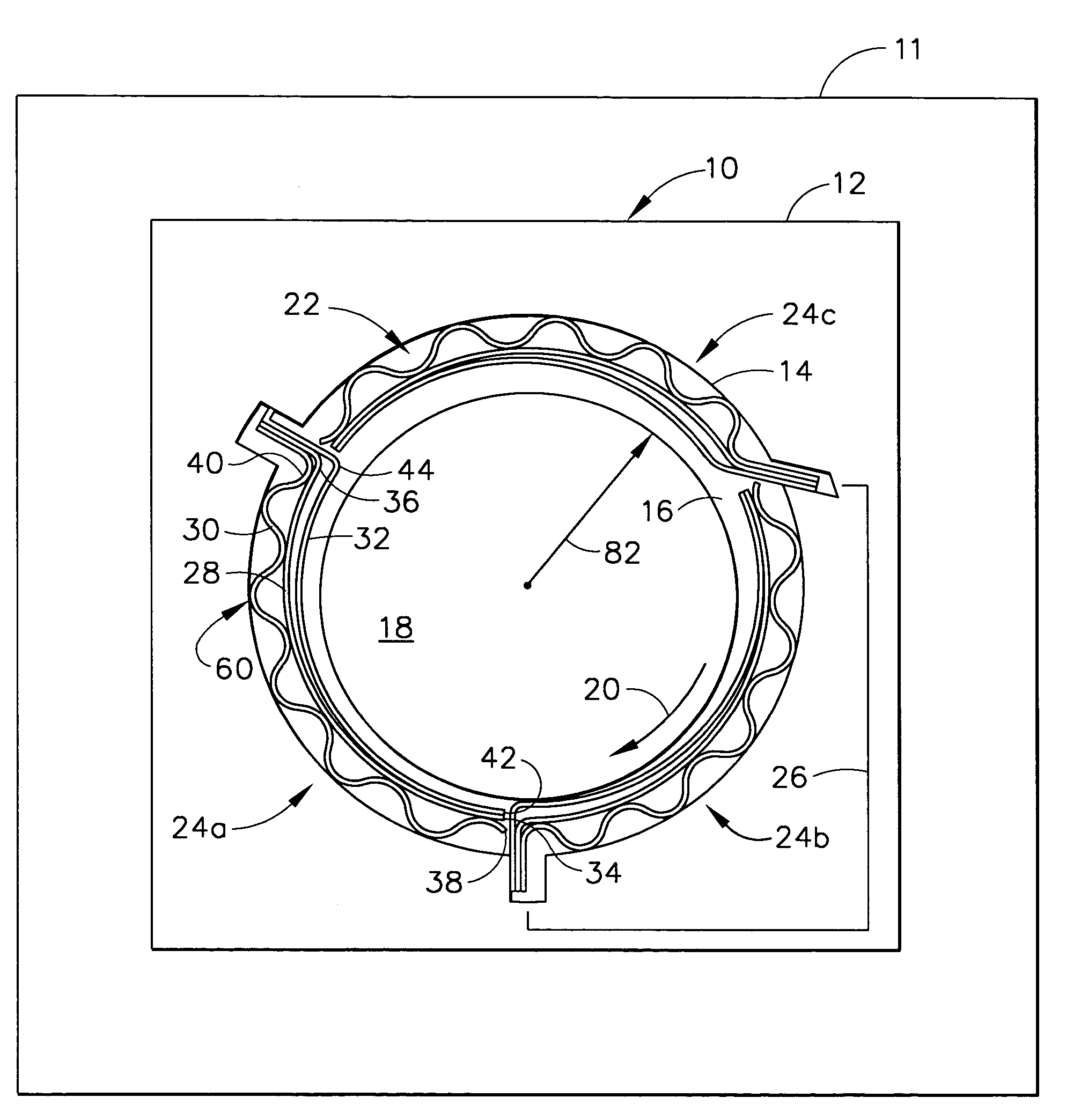
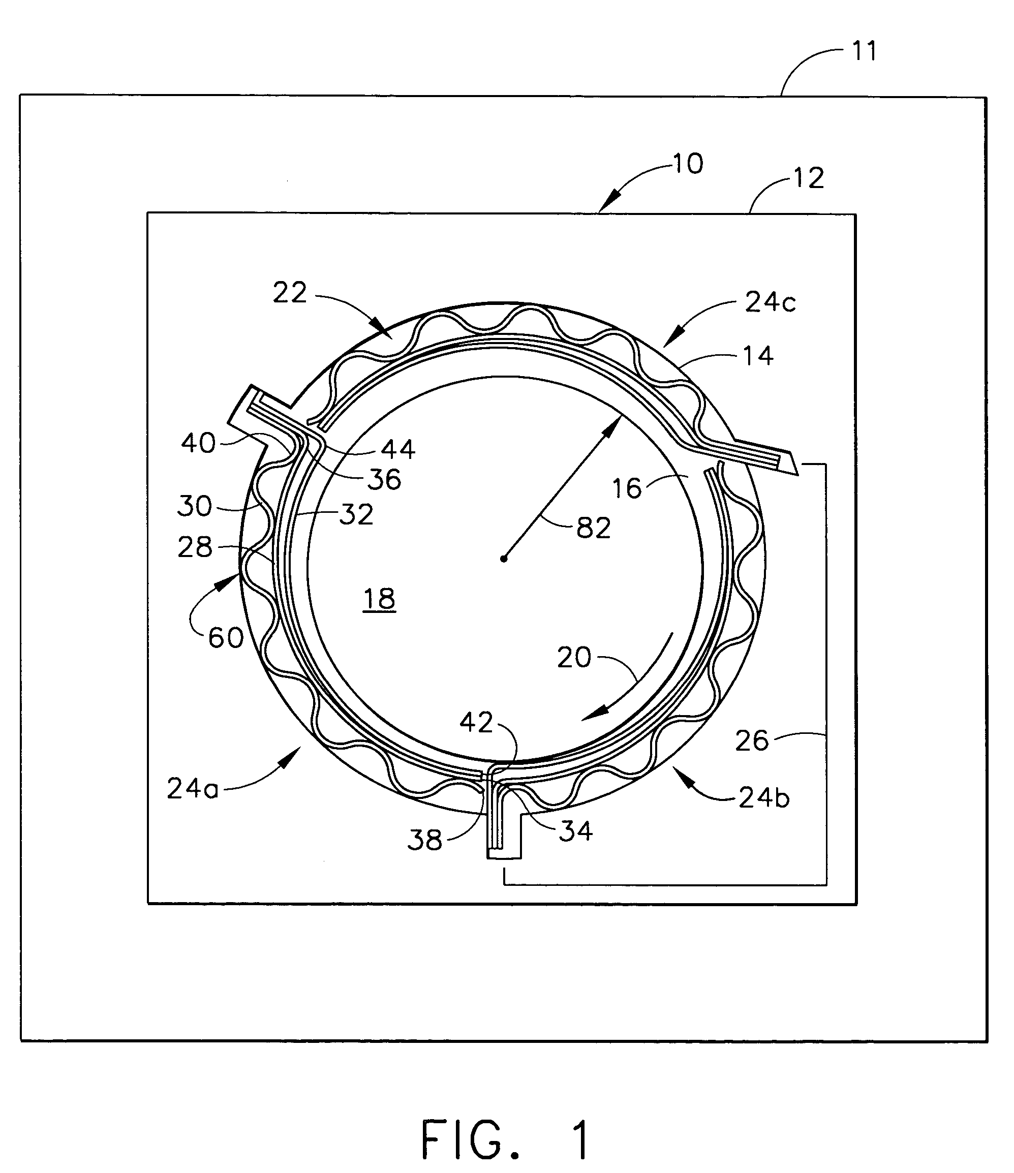
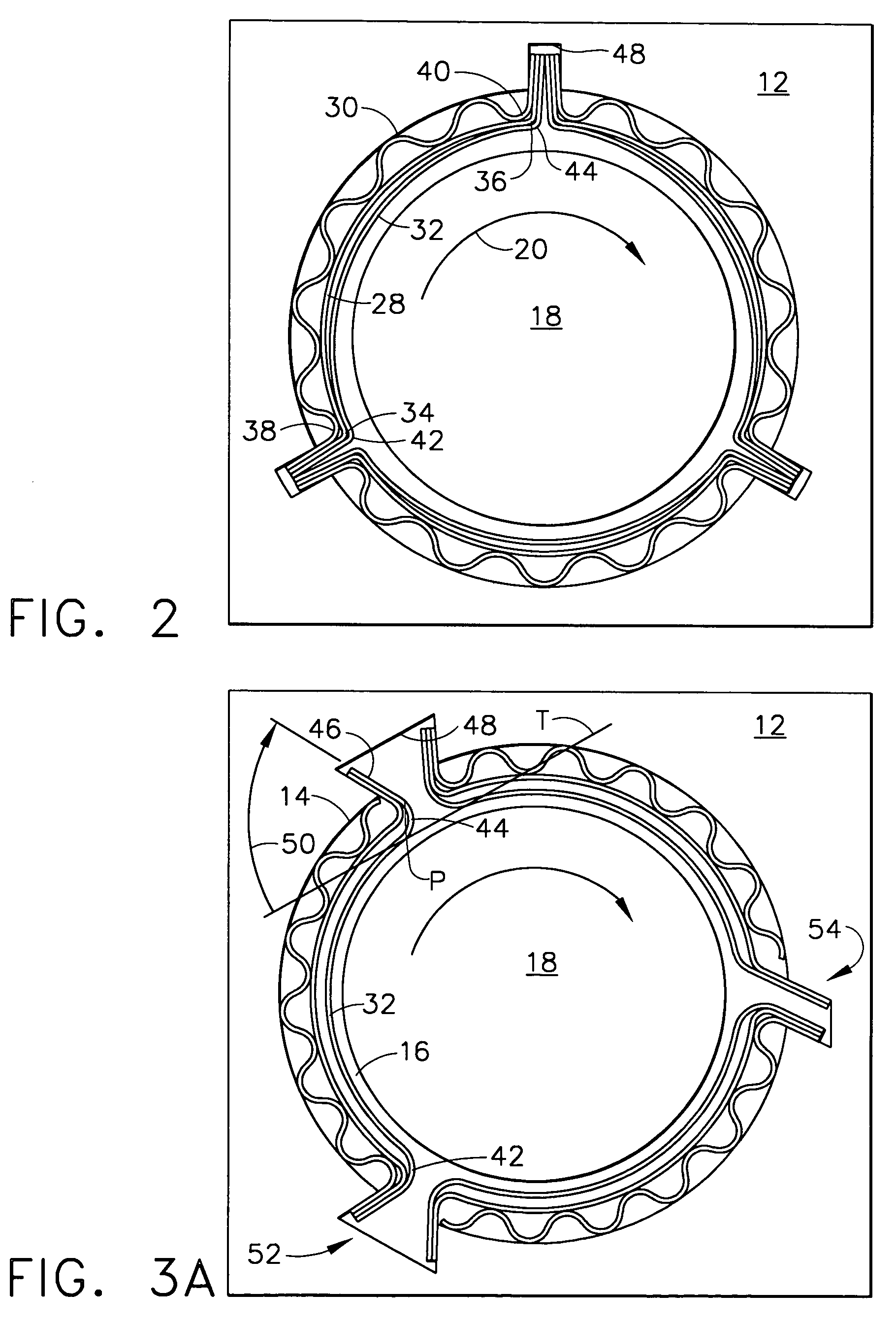
A journal foil bearing comprising a retaining member having an inner surface which defines a shaft opening within which a rotatable shaft is receivable for rotation; and a foil assembly affixed to and lining the inner surface and comprising a plurality of foil sub-assemblies each subtending a circumferential segment, of the inner surface. Each of the foil sub-assemblies may comprise an under foil sandwiched between a spring foil disposed radially outwardly of the under foil, and a top foil disposed radially inwardly of the under foil, the under foil, the top foil, and the spring foil each having a leading edge distal from a trailing edge in a direction of rotation of the rotatable shaft, and each of the under foil, the top foil, and the spring foil being affixed to the retaining member along their respective leading edge, their respective trailing edge, or both their respective leading edge and their respective trailing edge, wherein a radius of curvature of the top foil is less than a radius of curvature of the under foil. A method of supporting a rotating shaft is also disclosed.

Description

BACKGROUND OF THE INVENTION[0001]The present invention generally relates to apparatus and methods related to a journal foil bearing. More specifically, to a journal foil bearing comprising multiple foils, wherein each may have a different radius of curvature.[0002]Fluid film hydrodynamic bearings may operate on the principle that a high speed rotating member, such as a shaft, is at least slightly eccentric with respect to rotation about its longitudinal axis. Therefore, if the shaft is enclosed by a close-fitting, compliant, annular element such as a thin foil encased within a stationary retaining member, the eccentricity of rotation within such retaining member will form and maintain a pressurized fluid (e.g., air) film between the shaft and the compliant foil. The high speed rotation of the shaft generates a high pressure in the fluid film, which fluid film supports the load imposed by the shaft. The lowest rotational speed at which this occurs is known as the lift-off speed. A sp...

Claims


Application Information

Patent Timeline
Patent Type & Authority Patents(United States)
IPC IPC(8): F16C27/02F16C17/02
CPCF16C17/024F16C2360/24F16C27/02F16C43/02
Inventor KANG, SUN GOOSAVILLE, MARSHALLHURLEY, KEITH A.
Owner HONEYWELL INT INC
Why Eureka
Eureka Blog
Learn More