Timer relay control board

a control board and relay technology, applied in the field of heater control boards, can solve the problems of increasing human error, adding size and cost to heaters, adding time to wiring components, etc., and achieves the effects of reducing cost, reducing size and cost, and producing more quickly

Inactive Publication Date: 2009-06-30
MAXITROL
View PDF8 Cites 28 Cited by
  • Summary
  • Abstract
  • Description
  • Claims
  • Application Information

AI Technical Summary

Benefits of technology

[0009]The subject invention provides a controller for a heater that has several advantages over the prior art. First, the controller of the subject invention may be produced at a smaller size and lower cost than the controllers of the subject invention. In addition, the controller of the subject invention may be produced more quickly with less chance of human error.

Problems solved by technology

Specifically, the controllers of the prior art require many wires, adding size and cost to the heater.
Also, wiring the components adds time since each electrical component must be wired individually.
Wiring each electrical component individually subsequently increases human error.

Method used


Image

  • Timer relay control board
  • Timer relay control board
  • Timer relay control board

Examples


Embodiment Construction

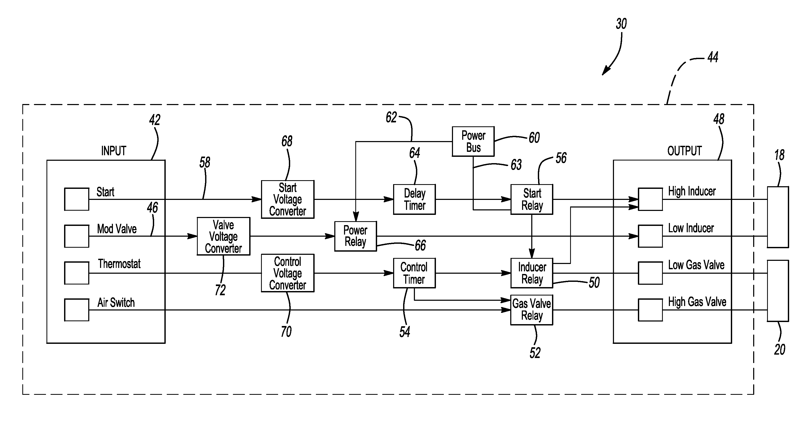
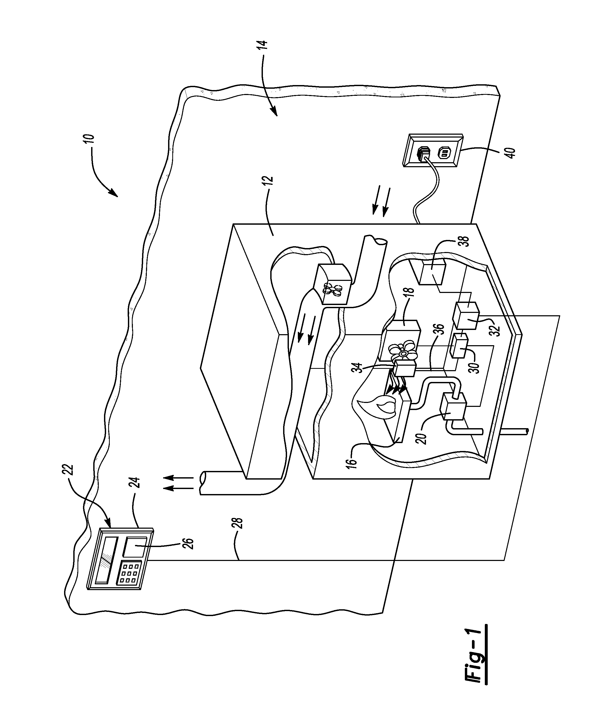
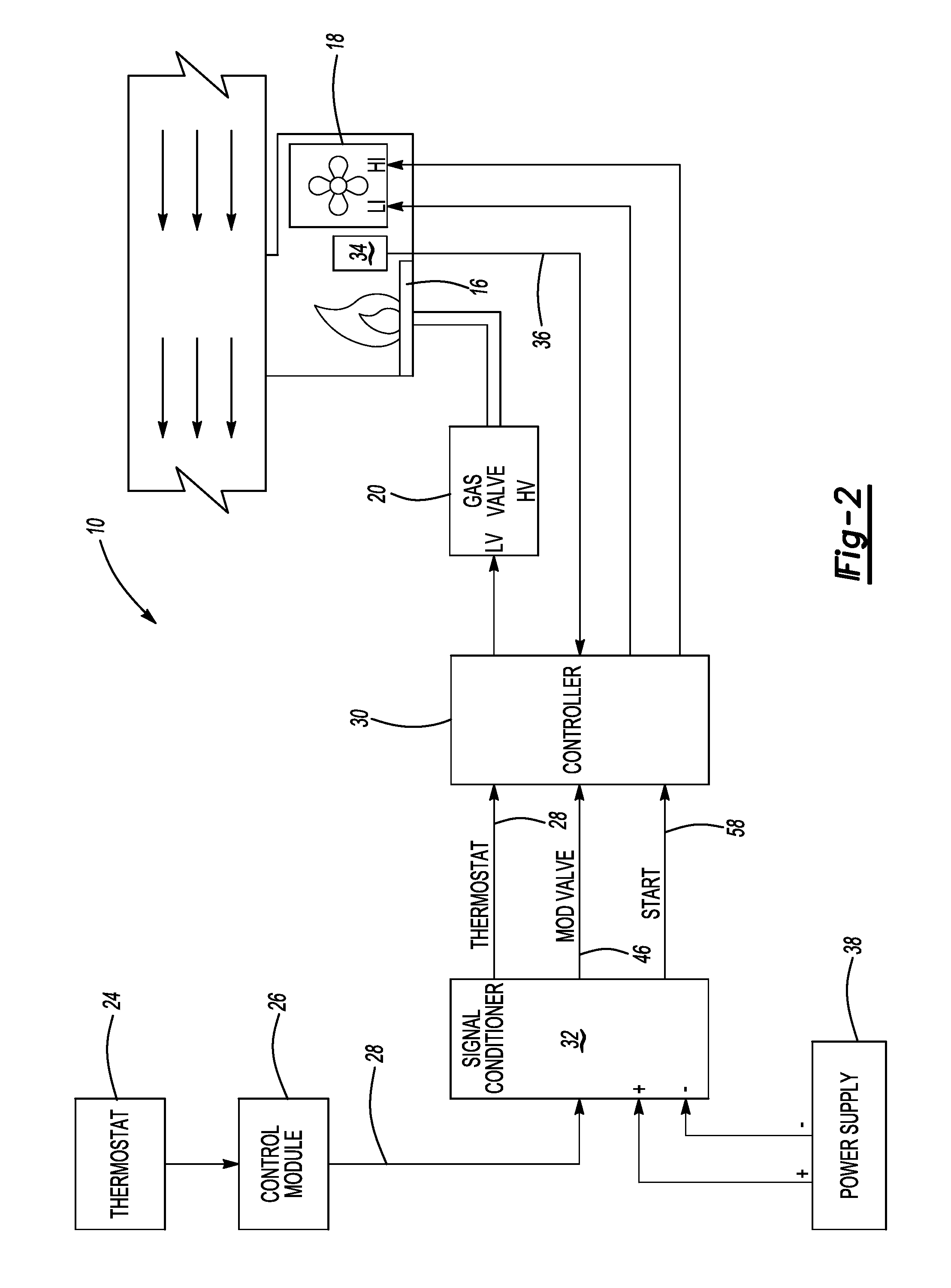
[0015]Referring to the Figures, wherein like numerals indicate corresponding parts throughout the several views, a control system 10 for a heater 12 located in an environment 14, such as a furnace in a building, is shown generally in FIG. 1. Referring now to FIGS. 1 and 2, the heater 12 may include a burner 16. The heater 12 may also include an inducer 18 to provide the burner 16 with combustion air. The inducer 18 may be any type of inducer 18 known in the art having at least a high speed stage and a low speed stage. During the high speed stage, the inducer 18 provides the burner 16 with a greater amount of combustion air than during the low speed stage. The heater 12 may further include a valve 20 in fluid communication with the burner 16 to provide the burner 16 with a fuel, such as gas. The valve 20 is any type of valve known in the art and may operate under a high flow stage and a low flow stage. During the high flow stage, the valve 20 provides the burner 16 with a greater amo...


PUM


Abstract

A heater (12) includes a burner (16), a valve (20), and an inducer (18). A thermostat (24) is electrically coupled to the heater (12) and a control board (44) is disposed in the heater (12) and electrically connected to the thermostat (24). The control board (44) includes an inducer relay (50), a valve relay (52), and a control timer (54) for switching the valve (20) between a high flow stage and a low flow stage and the inducer (18) between a high speed stage and a low speed stage, respectively, wherein the inducer relay (50), the valve relay (52), and the control timer (54) are mounted to the control board (44) to define a singular and compact controller (30).

Description

CROSS REFERENCE TO RELATED APPLICATION[0001]This application claims the benefit of application Ser. No. 60 / 704,549 filed Aug. 2, 2005.BACKGROUND OF THE INVENTION[0002]1. Field of the Invention[0003]The subject invention relates to a controller for a heater.[0004]2. Description of the Prior Art[0005]Various types of controllers for heaters are known in the art. These controllers include electromechanical components to control a valve and an inducer. Once such heater is shown in U.S. Pat. No. 5,326,025 (the '025 patent). The '025 patent discloses a controller electrically connected to an inducer relay that switches the inducer between a high speed stage and a low speed stage. In addition, the '025 patent discloses a controller that switches the valve between a high flow stage and a low flow stage.[0006]Although the controllers of the prior art may be enjoyed by a wide variety of people, there remains an opportunity to improve upon the controllers of the prior art to define a singular ...

Claims


Application Information

Patent Timeline
Patent Type & Authority Patents(United States)
IPC IPC(8): F23N5/00
CPCF23N5/203F23N2023/22F23N2027/02F23N2223/22F23N2227/02
Inventor O'MARA, JASONSCHLACHTER, JOHN JAMES
Owner MAXITROL
Why Eureka
Try Eureka