Automated dispenser

a dispenser and automatic technology, applied in the field of dispensers, can solve the problems of high power consumption, consuming power, and affecting the user's perception that the device is not detecting him/her properly, and achieve the effect of saving the power used by the sensor system and less power

Inactive Publication Date: 2009-06-30
SCA HYGIENE PROD AB
View PDF58 Cites 25 Cited by
  • Summary
  • Abstract
  • Description
  • Claims
  • Application Information

AI Technical Summary

Benefits of technology

[0014]The invention is based on the idea that the scanning rate, i.e. the number of scans performed per second, is made to vary upon the location of a user with respect to the dispenser, such that the dispenser operates at a first scanning rate (i.e. performs a scanning sequence by activating IR emitter and receiver circuits, and emitting single scanning pulses at a first number of single scans per second) when no possible / potential user is detected. The system then increases the scanning rate when a user is considered to be close to the dispenser (i.e. has entered a first detection zone). This variable scanning rate allows very low power to be used when no users are adequately close to the dispenser, and only to use a higher power level when required, so that a quick reaction time to dispense a product is experienced by the user.
[0015]The invention thus provides a sensor system that creates a first detection zone which, when entered by a possible user, causes the scanning rate to change from a first lower scanning rate to a second higher scanning rate.
[0017]Alternatively, the same set of sensors which are used to cause the dispenser to dispense a product can also be used to detect a user entering a first detection zone and to include a control system which changes the scanning rate from the first slower rate to the second higher rate. In this way, a user approaching the dispenser (e.g. 40 to 50 cm or perhaps further away from the dispenser) will activate the sensor system to change the scanning rate to a higher scanning rate and as the user continues to move his hands and / or body closer to the discharge outlet of the dispenser, the user will be detected as being in a “dispensing zone” and will thus cause the dispenser to dispense a product (e.g. a paper hand towel).
[0019]When a user moves away from the dispenser, the scanning rate can then be decreased again to a lower rate, thereby consuming less sensor operation power.
[0020]As will be apparent, even at relatively short distances for the first detection zone (e.g. up to about 50 cm from the dispenser for example in a 30° to 60° slanted forwards and downwards direction) it will be understood that the system has significant power saving advantages while still allowing a good reaction time to dispense a towel. This is because the user expects to move his / her hands relatively close to the device in order for dispensing to occur, and this takes on the order of between a quarter and half a second at normal hand movement speeds (between 0.2 m / s and 0.5 m / s), by which time the dispenser can be made to be already scanning at the second higher rate (or even a still higher rate) and thus be able to dispense very close to the time when the hands are in an “expected” position for dispensing (i.e. a position at which the user would expect a towel to be dispensed, typically some 15 to 25 cm from the dispenser outlet).
[0022]Advantageous use can be made of the varied scanning rate by making the first scanning rate between e.g. 0.15 and 0.25 seconds between scans (i.e. the scanning rate when a possible user is outside the first detection zone), or even longer (such as between 0.25 and 0.5 seconds), and the second scanning rate of the order of about 0.08 to 0.12 seconds between scans and requiring only two consecutive scans (or e.g. two out of three consecutive scans) providing a reflected IR level above background IR level to activate dispensing. Such dispensing will be perceived by the user as almost immediate, yet a significant amount of power used by the sensor system can be saved due to the initial low scanning rate which consumes less power.

Problems solved by technology

This high scanning rate means however that power is being consumed at a high level since the IR emitters and detectors need to be activated very often and these consume power when active.
Using a lower scanning rate would of course save power, but the time to dispense a towel would then be longer, and when the user moves his / her hands towards the dispenser rapidly after washing, this can give the impression to the user that the device is not detecting him / her properly if a towel is not dispensed immediately.

Method used


Image

  • Automated dispenser
  • Automated dispenser
  • Automated dispenser

Examples


Embodiment Construction

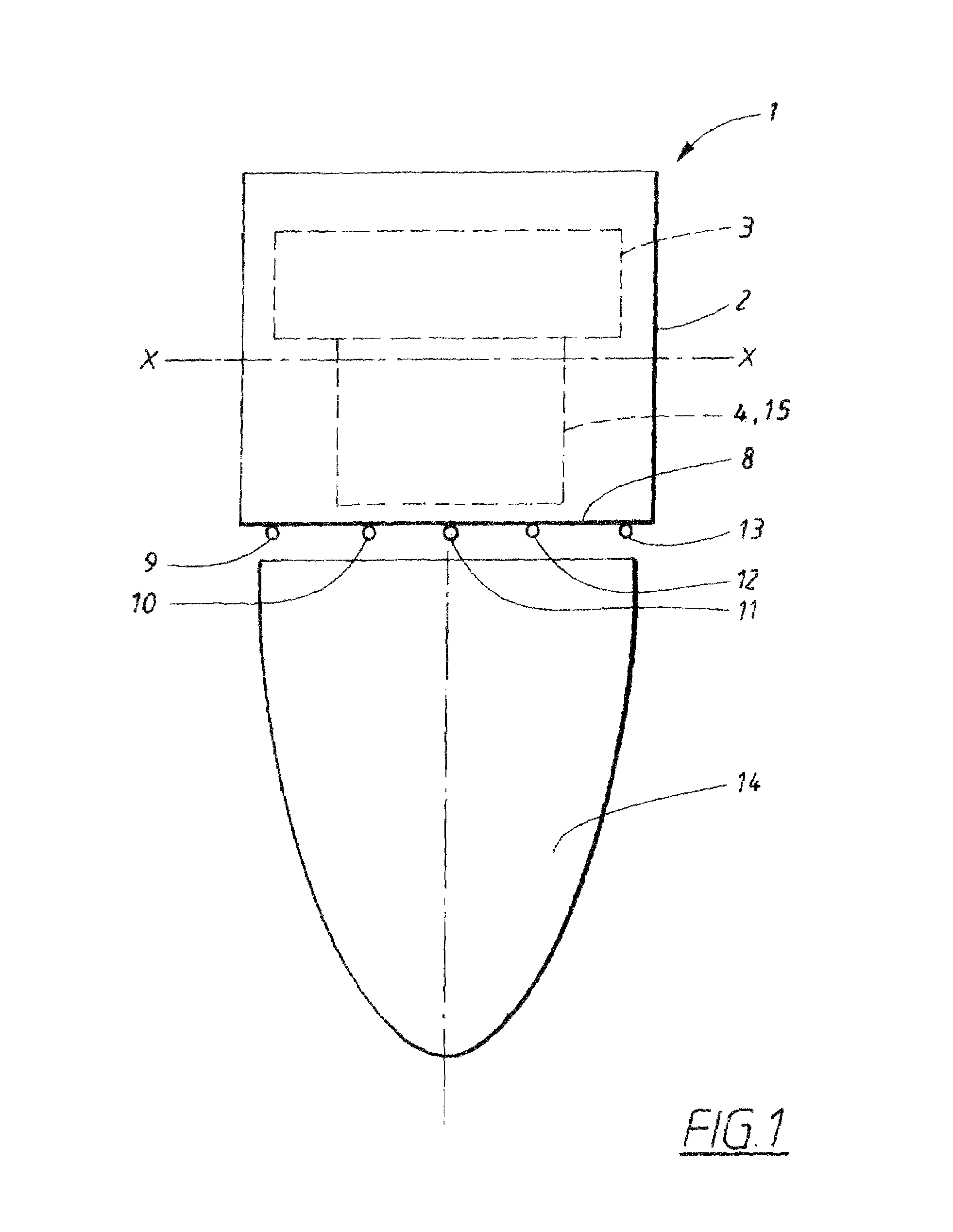
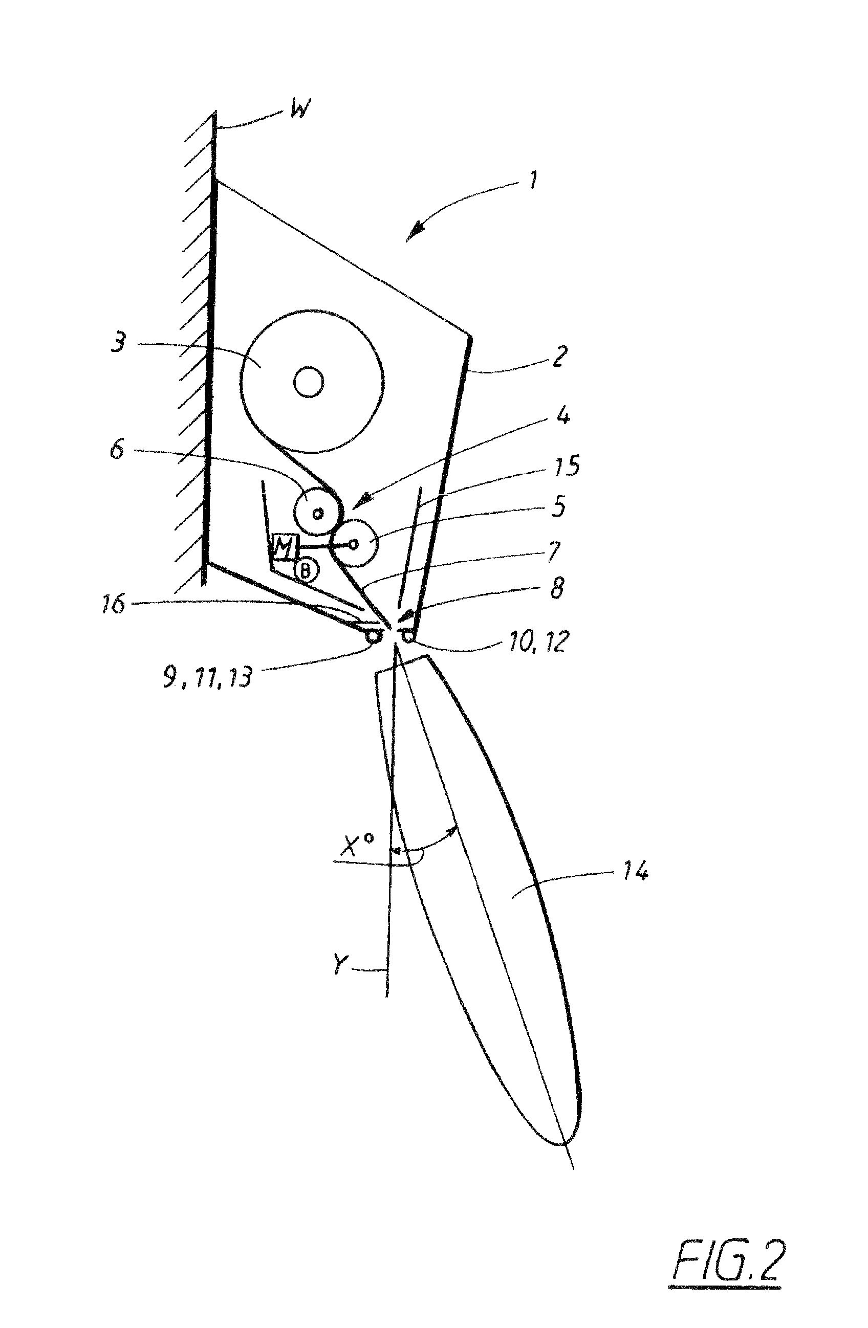
[0032]FIG. 1 and FIG. 2 show a dispenser 1 in front and side views respectively, whereby FIG. 2 shows the dispenser 1 attached at its rear side to a wall (the means of attachment are not shown but may be of any suitable type such as screws, adhesive, adhesive tape, or other attachment means).

[0033]The dispenser 1 comprises a housing 2, within which is located a product supply, in this case a supply of paper in a roll 3. The roll is suitably a roll of continuous non-perforated paper, but may also comprise perforated paper in some cases. Also located in the housing 2 is a paper transport mechanism 4, preferably in the form of a modular drive cassette with its own casing 15, which can preferably be removed as a single unit from the housing 2 when the housing is opened.

[0034]FIG. 1 shows the paper roll 3 and the transport mechanism 4 as simple blocks for the sake of simplicity. Likewise, FIG. 2 shows the paper roll 3 and the transport mechanism 4 in a vastly simplified form, whereby the...


PUM


Abstract

An automatic dispenser for dispensing lengths of paper for use as hand towels, includes an IR sensor system for detecting a user. The sensor system scans at a first scanning rate and also at a second higher scanning rate. When the sensor system detects a user, it changes the scanning rate from the first to the second rate. The dispenser aims at reducing power consumption while providing improved reaction time when required to dispense paper.

Description

CROSS REFERENCE TO RELATED APPLICATION[0001]This is a continuation of international application PCT / EP2005 / 007617 filed on 13 Jul. 2005, which designated the United States of America.FIELD OF THE INVENTION[0002]The present invention relates generally to a dispenser, in particular of the type including a motor-driven dispensing system combined with control circuitry for sensing the presence of a possible user and controlling operation of said motor to effect dispensing of material. The invention furthermore relates even more particularly to an automatic towel dispenser (preferably paper towels stored inside the dispenser housing) of the electrically powered type (particularly of the DC battery powered type, but which may also be an AC-powered type or a combination of AC and DC power types) in which paper sheets such as paper hand-towels are dispensed when the presence of said possible user is detected to fulfill the condition of being within a specified zone, without physical contact...

Claims


Application Information

Patent Timeline
Patent Type & Authority Patents(United States)
IPC IPC(8): G01J5/00
CPCA47K10/36H03K17/943H03K17/955H03K2217/94031H03K2217/94108H03K2217/94116A47K10/3612A47K10/3625A47K2010/3668
Inventor MOK, KIN LUNMOK, KING LUNGNG, HONG
Owner SCA HYGIENE PROD AB
Why Eureka
Try Eureka