Utility meter antenna for ground mounted meter boxes

a technology for utility meters and meter boxes, applied in the direction of subaqueous/subterranean adaption, sustainable buildings, instruments, etc., can solve the problems of meter readers, inconvenience to homeowners, and especially acute problems, and achieve the effect of improving the transmission characteristics of communication devices

Active Publication Date: 2009-06-30
SENSUS SPECTRUM LLC
View PDF13 Cites 23 Cited by
  • Summary
  • Abstract
  • Description
  • Claims
  • Application Information

AI Technical Summary

Benefits of technology

[0012]The transmitter further includes a metallic isolation sleeve aligned with the radiating trace formed on the circuit board. In one embodiment of the invention, the isolation sleeve is mounted to the exterior surface of the transmitter post in general alignment with the transmission element contained within the transmitter post. The isolation sleeve functions to enhance the performance of the transmitter and reduce the signal attenuation caused by the meter pit. Specifically, the isolation sleeve enhances the performance of the transmitter when the transmitter is utilized with various different types of pit lid materials. The isolation sleeve provides impedance matching between the internal radiating trace on the printed circuit board and the radiating antenna. The use of the metallic isolation sleeve reduces the external influences of the pit lid, regardless of whether the pit lid is formed from plastic, composite or various different metals. The isolation sleeve provides the internal transmission element with the same tuning or impedance matching characteristics as a metallic pit lid. This function is extremely beneficial when the antenna is utilized with a non-metallic pit lid.
[0013]In addition, the isolation sleeve redirects the transmission element, and specifically the lower lobe of the PCB-mounted dipole antenna, and forces the energy toward the radiating plate of the radiating antenna. This feature is accomplished by the geometry, size and position of the isolation sleeve relative to both the transmission element and the antenna radiator. The position and geometry of the isolation sleeve provides the impedance matching necessary for improved communications.
[0014]In addition, the isolation sleeve reduces the amount of energy escaping from the transmission element into the meter pit, which otherwise causes undesired resonant frequencies in metal pits. Since there are many different types of pits, the isolation sleeve functions to isolate the resonance frequencies for all different types of meter pit configurations.
[0019]When the base of the antenna unit is installed onto the pit lid, the entire radiating antenna, including the ground plate, spacer and radiator plate are positioned above the top surface of the pit lid. The positioning of the entire radiating antenna above the pit lid reduces the effect the material of the pit lid has on the performance characteristics of the radiating antenna.
[0021]Once the transmitter post is fully inserted into the antenna unit, the transmitter housing is secured to the attachment section such that the transmitter is supported by the pit lid. When supported by the antenna unit, a portion of the transmitter post extends past the top surface of the pit lid. Thus, a portion of the transmitter extends out of the meter pit to further enhance the transmission characteristics of the communication device.

Problems solved by technology

A longstanding problem in the utility industry is the economic reading of utility meters without inconvenience to the homeowner.
The problem is especially acute in connection with the reading of water meters.
However, the reading of such meter installations presents a number of problems, such as the inconvenience to the homeowner as well as the inconvenience to the meter reader when the homeowner is not present at the time of the individual meter reading.
In addition, manual meter reading has a significant disadvantage in that it requires a large amount of manpower, leading to significant expense.
Further, meter readers may erroneously record the numeral values of the meter register or the homeowner may not be present at the time the meter reading is to take place.
When such arrangements are in use, material close to the antenna may affect the efficiency of the antenna in radiating the desired signals.
The use of pit-mounted antenna arrangements are often complicated by the type of material used to form the pit lid and the operating environment in the area surrounding the antenna.

Method used


Image

  • Utility meter antenna for ground mounted meter boxes
  • Utility meter antenna for ground mounted meter boxes
  • Utility meter antenna for ground mounted meter boxes

Examples


Embodiment Construction

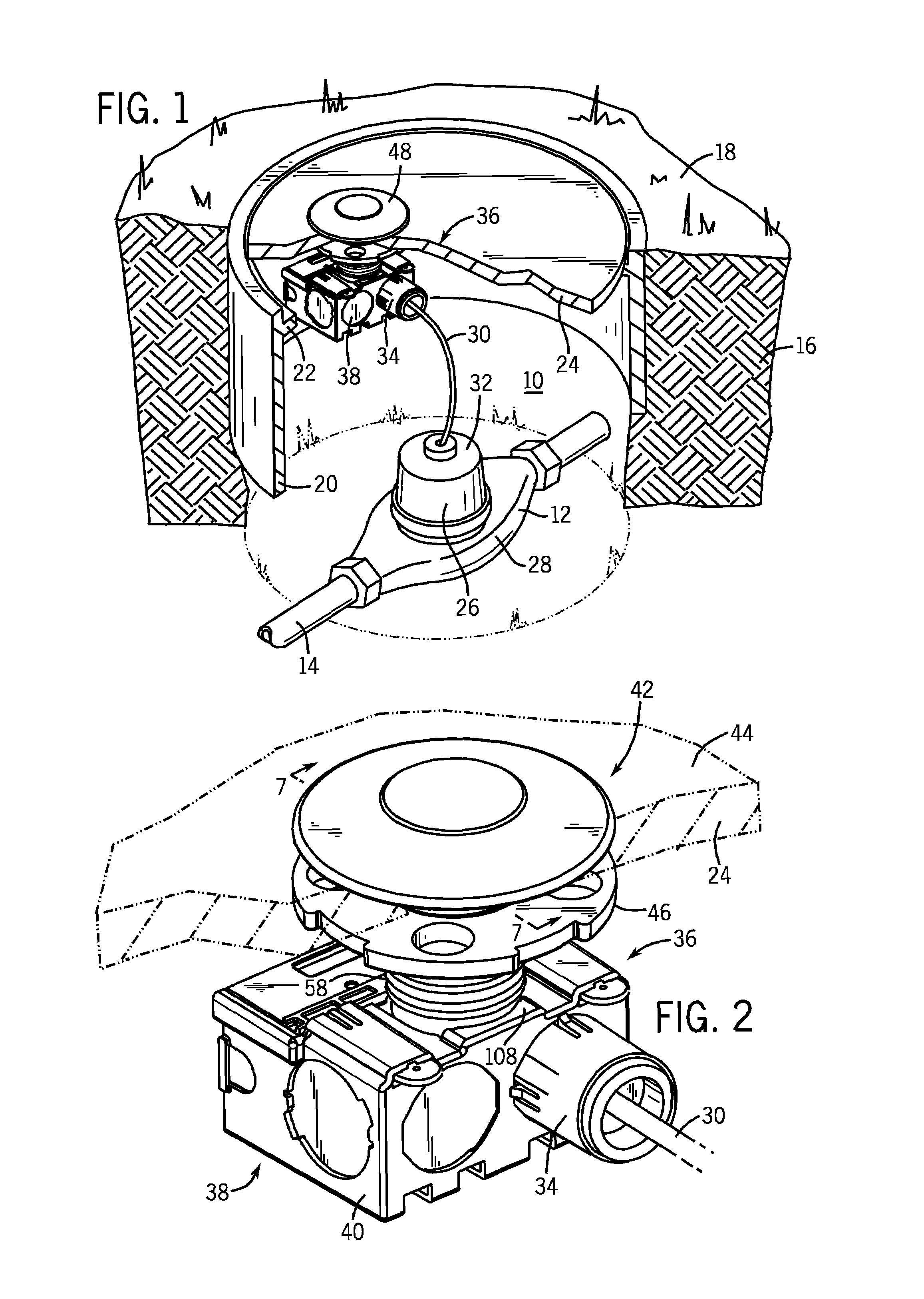
[0031]Referring first to FIG. 1, thereshown is a meter pit 10 that includes a utility meter 12. In the embodiment of the invention illustrated, the utility meter 12 is water meter that is positioned in a water supply line 14 buried within the ground 16 and extending through the meter pit 10. Although the utility meter 12 will be described throughout the following description as being a water meter, it should be understood that the utility meter 12 could be any of a variety of different types of meters for measuring different types of consumable commodities, such as gas, water, electricity of other types of similar commodities.

[0032]As illustrated in FIG. 1, a meter pit 10 extends below the ground surface 18 and is defined by a pit box 20. The pit box 20 is a cylindrical, metal enclosure that is submerged into the ground 16. The pit box 20 includes an upper ledge 22 that supports a pit lid 24. In the embodiment of the invention illustrated, the pit lid 24 is preferably formed from a ...


PUM


Abstract

A method and apparatus for transmitting utility meter data from an underground meter pit. The device includes a radiating antenna that is positioned entirely above the top surface of the pit lid. The radiating antenna conductively contacts a portion of the transmitter supported on the pit lid by the antenna housing. The transmitter housing includes an isolation sleeve that physically contacts a portion of the radiating antenna to enhance the signal transfer from the transmitter to the radiating antenna.

Description

BACKGROUND OF THE INVENTION[0001]The present invention generally relates to the automatic reading of utility meters. More specifically, the present invention is related to a method and apparatus for transmitting utility meter data from an underground meter pit using a removable pit lid and antenna.[0002]A longstanding problem in the utility industry is the economic reading of utility meters without inconvenience to the homeowner. The problem is especially acute in connection with the reading of water meters. In geographic areas that are subject to freezing temperatures, it has in the past been necessary to install meters within the residence to prevent damage to the meter when the temperature drops such that the water within the meter freezes. However, the reading of such meter installations presents a number of problems, such as the inconvenience to the homeowner as well as the inconvenience to the meter reader when the homeowner is not present at the time of the individual meter r...

Claims


Application Information

Patent Timeline
Patent Type & Authority Patents(United States)
IPC IPC(8): G08B23/00
CPCG01D4/002H01Q1/2233Y02B90/241Y04S20/32Y02B90/20Y04S20/30
Inventor VERKLEEREN, JEFFZAYAK, JOHNPAUN, CRISTIANZIMMERMAN, MIKE
Owner SENSUS SPECTRUM LLC
Why Eureka
Try Eureka