Color solid-state image pickup device

a solid-state image and pickup device technology, applied in semiconductor/solid-state device details, radio control devices, television systems, etc., can solve the problems of deterioration of image quality in terms of color reproducibility and noise, failure to effectively utilize, and filtering of complementary color systems, so as to improve the reliability of image pickup devices.

Active Publication Date: 2009-06-30
FUJIFILM CORP
View PDF17 Cites 24 Cited by
  • Summary
  • Abstract
  • Description
  • Claims
  • Application Information

AI Technical Summary

Benefits of technology

[0021]The present invention aims at providing a color solid-state image pickup, especially an MOS color solid-state image pickup device, which is easy to manufacture, can ensure a wide area for light-receiving sections on the surface of a semiconductor substrates, obviates a necessity for color signal separation computation processing, and enables an easy attempt to enhance quality of a photographed image.
[0022]The present invention also aims at providing a color solid-state image pickup device, especially a CCD color solid-state image pickup device, which enables an attempt to enhance sensitivity and image quality.

Problems solved by technology

Thus, color filters of this type suffer a problem of waste of G and R incident light rays and a failure in effective utilization thereof.
Hence, when compared with a solid-state image pickup device using color filters of a primary color system capable of directly obtaining signals of R, G, and B color components, the solid-state image pickup device using the filters of complementary color system suffers a problem of deterioration of image quality in terms of color reproducibility and noise.
Since the solid-state image pickup does not employ color filters, spectra of color component output signals (R, G, B) mutually become larger, thereby causing overlaps.
This also presents a problem of difficulty in faithful color reproduction and an attempt to enhance image quality.
Hence, photographing an image with the same sensitivity as that ever achieved becomes more difficult.

Method used


Image

  • Color solid-state image pickup device
  • Color solid-state image pickup device
  • Color solid-state image pickup device

Examples


first embodiment

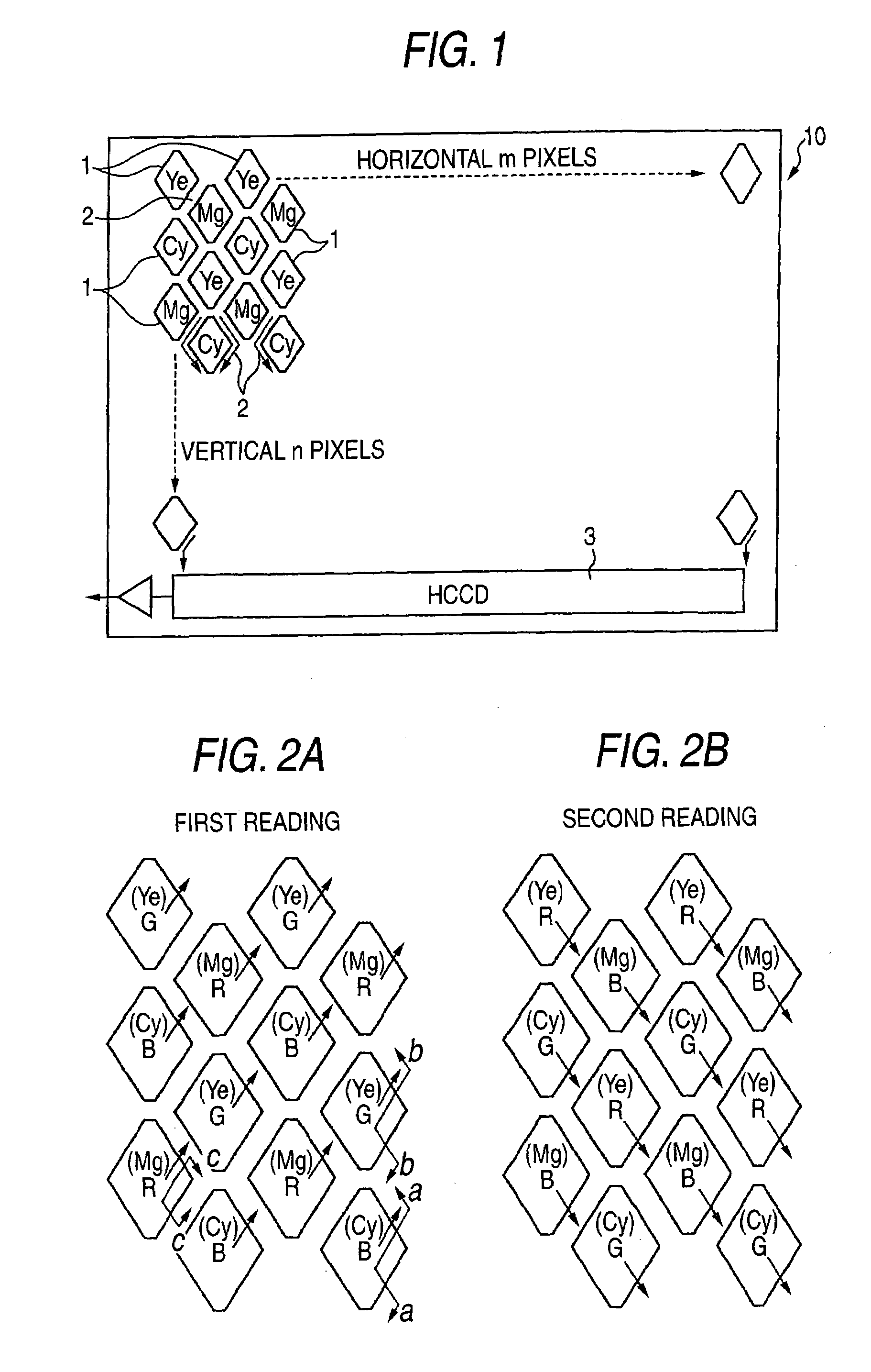
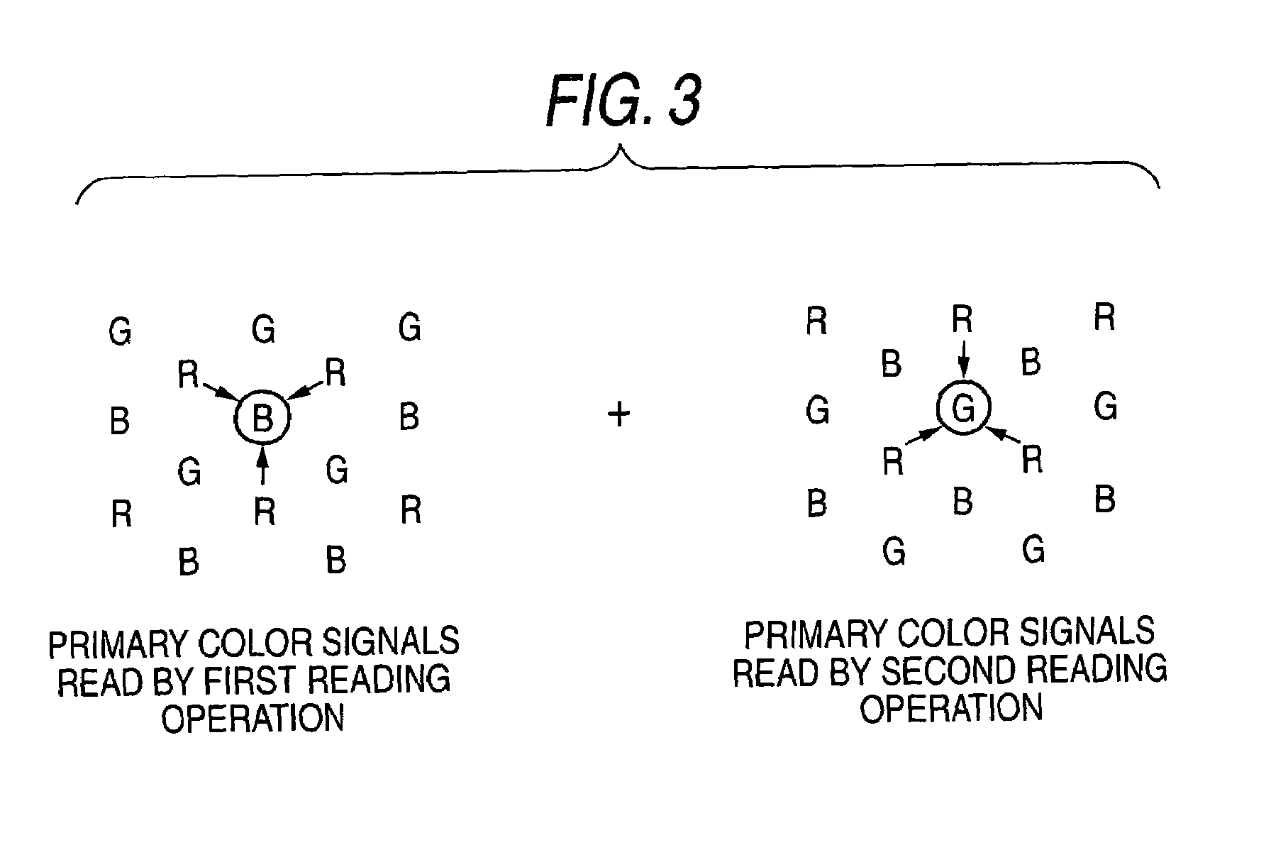
[0130]FIG. 1 is a schematic surface view of a CCD color solid-state image pickup of single plate type according to a first embodiment of the invention. In the CCD color solid-state image pickup, a plurality of light-receiving sections 1, each having a cross-sectional structure to be described in detail later, are formed in an array on the surface of a semiconductor substrate 10. In an illustrated example, each light-receiving section 1 is depicted as a rhombus.

[0131]The arrangement of pixels employed in the present embodiment corresponds to the arrangement of pixels described in JP-A-10-136391; that is, a so-called honeycomb pixel arrangement in which the respective light-receiving sections 1 are offset at half a pitch in both the vertical and horizontal directions. A vertical transfer path [e.g., a vertical charge-coupled device (VCCD)]2 (signal reading unit) is formed between adjacent light-receiving sections 1, and signal electric charges read to the vertical transfer path 2 from...

second embodiment

[0160]FIG. 10 is a schematic surface view of a CCD color solid-state image pickup device of single plate type according to a second embodiment of the invention. In the following embodiment, unless otherwise specified, the dopant content of the N+ layer or the like and the depth of the storage layer are the same as those described in connection with the first embodiment.

[0161]In FIG. 10, a light-receiving section 21 is represented as a rectangle, and a plurality of light-receiving sections 21 are arranged in an array pattern. In this embodiment, the light-receiving sections 21 are arranged in a square grid pattern. A vertical transfer path 22 (signal reading unit) is formed between horizontally-adjacent light-receiving sections 21. Signal charges read from the light-receiving section 21 to the vertical transfer path 22 are transferred to a horizontal transfer path 23 provided at a downward location.

[0162]Complementary color filters; that is, the Ye filter and the Cy filter, are stack...

third embodiment

[0184]FIG. 16 is a schematic surface view of a CCD color solid-state image pickup device of single plate type according to a third embodiment of the invention. In the drawing, a light-receiving section 51 is represented by a rectangle, and a plurality of light-receiving sections 51 are arranged in an array. In the embodiment, the light-receiving sections 51 are arranged in a square grid pattern. A vertical transfer path 52 (signal reading unit) is formed between horizontally-adjacent light-receiving sections 51. Signal electric charges read from the light-receiving section 51 to the vertical transfer path 52 are transferred to a horizontally transfer path 53 placed at a downward position.

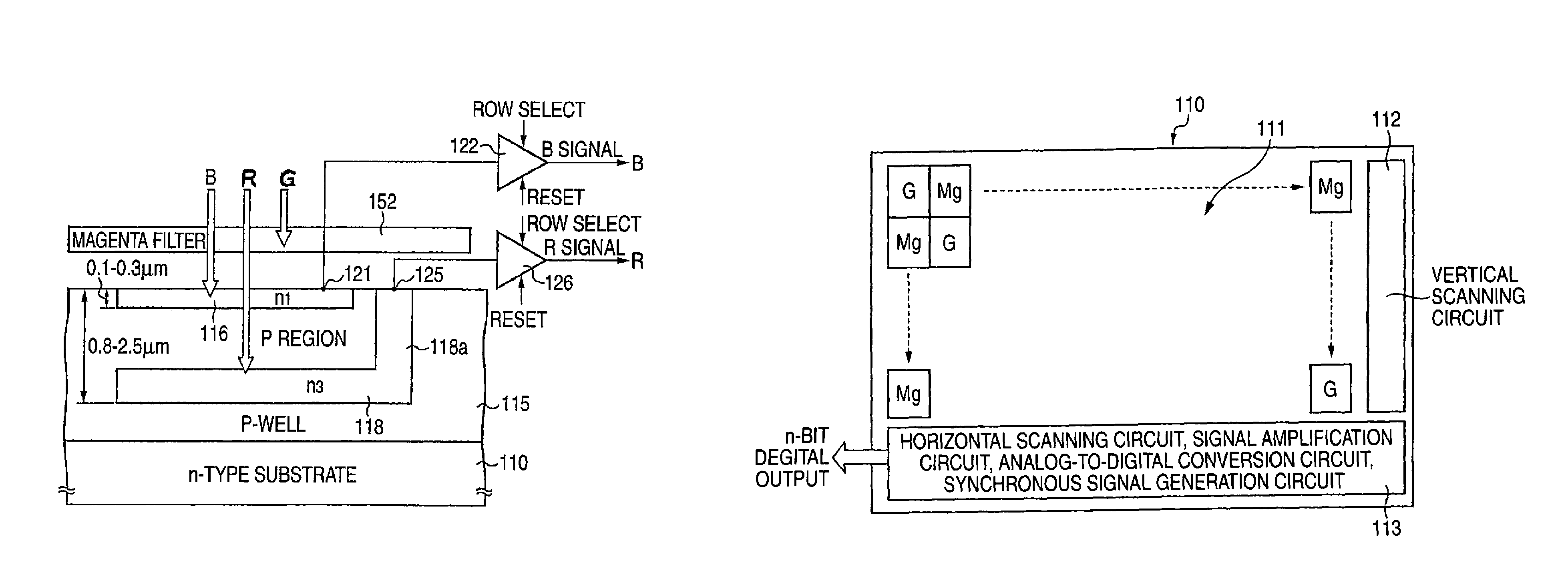
[0185]A green (G) filter, which is one of the filters of primary colors, and a magenta (Mg) filter, which is one of the filters of the complementary color system, are alternately stacked on the light-receiving sections 51 of the present embodiment in both the vertical and horizontal directions. In t...


PUM


Abstract

A color solid-state image pickup device comprises a plurality of light-receiving sections being arranged on the surface of a semiconductor substrate; complementary color filters which are stacked on all or portions of the plurality of light-receiving sections, each complementary color filter blocking incident light of one color of the three primary colors, to thereby permit transmission of incident light of remaining two colors; at least first and second color signal detecting layers which have the complementary color filters stacked thereon and are formed so as to be separated in a depthwise direction of the light-receiving section, the first and second signal detecting layers detecting a respective color signal of the light of two colors having passed through the complementary color filters; and a signal reading unit for reading the respective color signals in a distinguished manner, the signal reading unit being connected to the respective color signal detecting layers.

Description

[0001]This Nonprovisional application claims priority under 35 U.S.C. § 119(a) on Patent Application No(s). 2003-065617 and 2003-072102 both filed in JAPAN on Mar. 11, 2003 and Mar. 17, 2003, the entire contents of which are hereby incorporated by reference.BACKGROUND OF THE INVENTION[0002]1. Field of the Invention[0003]The present invention relates to a color solid-state image pickup device.[0004]2. Description of the Related Art[0005]In relation to a CCD (charge-coupled device) semiconductor solid-state image pickup element and a CMOS semiconductor solid-state image pickup element, as described in, e.g., U.S. Pat. No. 3,971,065, which will be described below, color filters having different spectral transmission factors are stacked on a plurality of photodiodes arranged in a two-dimensional array, thereby enabling pickup of a color image.[0006]Two types of color filters are available: namely, red (R), green (G), and blue (B) color filters of a primary color system; and color filter...

Claims


Application Information

Patent Timeline
Patent Type & Authority Patents(United States)
IPC IPC(8): H04N3/14H01L27/146H01L27/148H04N9/04
CPCH01L27/14868H04N9/045H01L27/14647H01L27/14812H04N2209/047H01L27/14627H01L27/14623H04N25/136
Inventor SHIZUKUISHI, MAKOTO
Owner FUJIFILM CORP
Why Eureka
Try Eureka