
Optical pickup device with a tilt adjusting actuator

a technology of optical pickup device and actuator, which is applied in the field of optical pickup device with tilt adjustment actuator, can solve the problems of difficult recording and reproducing high-quality signals on optical discs, magnetic interference between such electromagnetic devices, and unaddressed needs in the industry, and achieve the effect of eliminating any tilting of optical lenses

Inactive Publication Date: 2009-07-07
HON HAI PRECISION IND CO LTD
View PDF7 Cites 13 Cited by
  • Summary
  • Abstract
  • Description
  • Claims
  • Application Information

AI Technical Summary

Benefits of technology

This solution effectively compensates for the tilt angle of the optical disc, ensuring high-quality signal recording and reproduction by eliminating the need for additional electromagnetic devices, thereby reducing magnetic interference and improving signal quality.

Problems solved by technology

As such, it becomes difficult to record and reproduce high-quality signals on the optical disc.
If the optical pickup 100 has another electromagnetic adjusting device besides the electromagnetic tilt adjusting device, a magnetic interference may arise between such electromagnetic devices.
Therefore, a heretofore unaddressed need exists in the industry to address the aforementioned deficiencies and inadequacies.

Method used


Image

  • Optical pickup device with a tilt adjusting actuator
  • Optical pickup device with a tilt adjusting actuator
  • Optical pickup device with a tilt adjusting actuator

Examples


Embodiment Construction

[0015]Reference will now be made to the drawing figures to describe the preferred embodiments of the present optical pickup device, in detail.

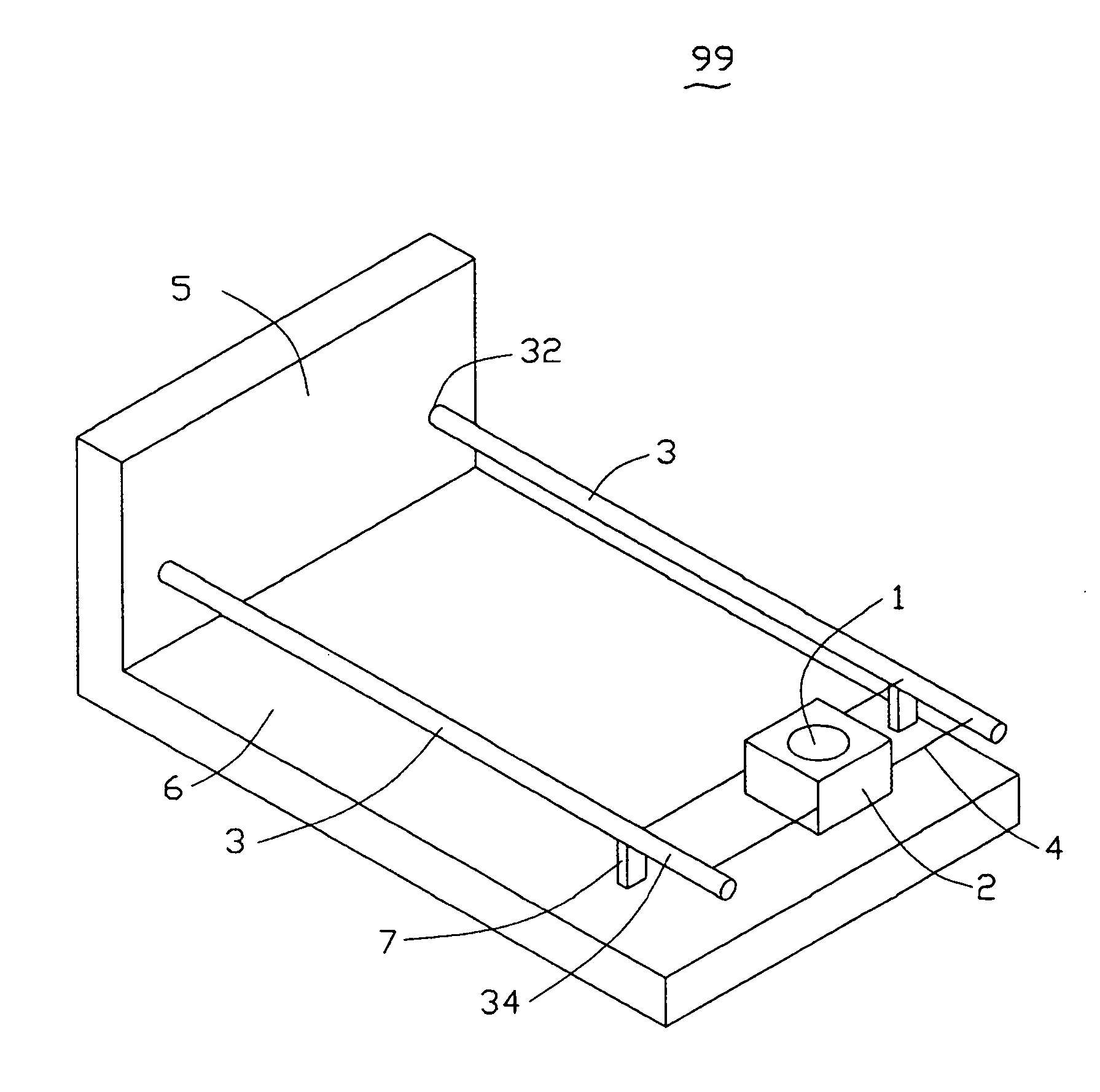
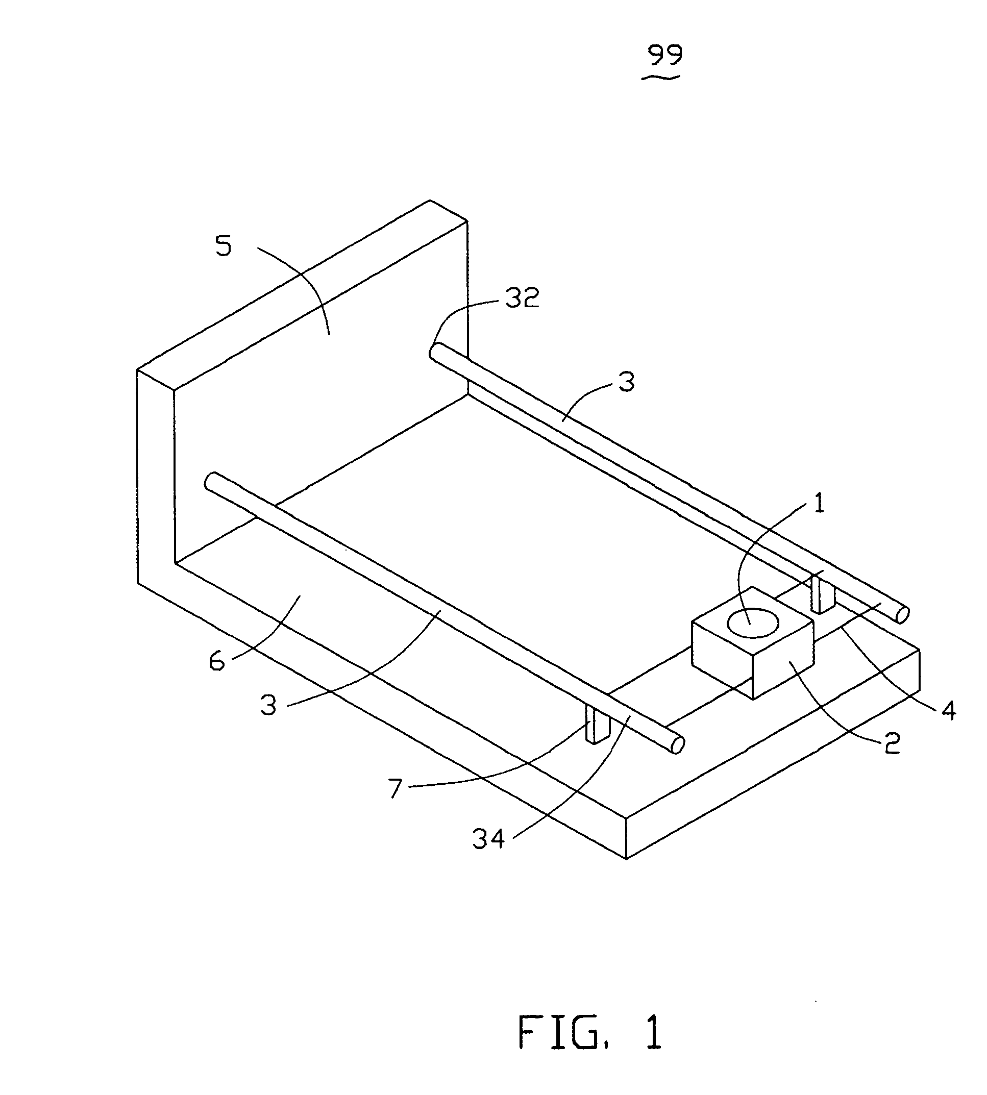
[0016]Referring to FIG. 1, an optical pickup device 99 includes a lens 1, a lens holder 2, a pair of cantilever beams 3, several wires 4, a supporting wall 5, a base plate 6, and a pair of piezoelectric member 7. The supporting wall 5 perpendicularly extends from a side of the base plate 6. Respective fixing ends 32 of the pair of cantilever beams 3 are fixed in and / or attached to the supporting wall 5, while free ends 34 of the cantilever beams 3 are supported by a pair of piezoelectric members 7. The piezoelectric members 7 are sandwiched between the base plate 6 and the free ends 34 of the cantilever beams 3. The lens 1 is held by the lens holder 2, while the lens holder 2 is suspended on the free ends 34 of the pair of cantilever beams 3 by the several wires 4. Two polarizing ends 72, 74 of the piezoelectric members 7 are respectively conn...


PUM

PropertyMeasurementUnit
angleaaaaaaaaaa
lengthaaaaaaaaaa
electric poweraaaaaaaaaa

Abstract

An optical pickup device includes a lens, a base plate, a supporting wall substantially perpendicular extending from the base plate, at least one cantilever beam, and at least one piezoelectric member. The lens is configured for converging a light beam onto an optical disc. The cantilever beam includes a fixing end and a free end. The fixing end is fixed in / attached to the supporting wall, and the free end suspends the lens thereat. The piezoelectric member is sandwiched between the free end and the base plate. The piezoelectric member is electrically polarizable along a polarization pivot thereof, and thus the length thereof along the pivot direction may be adjusted electrically. The polarization pivot is substantially perpendicular to the base plate and the cantilever beam.

Description

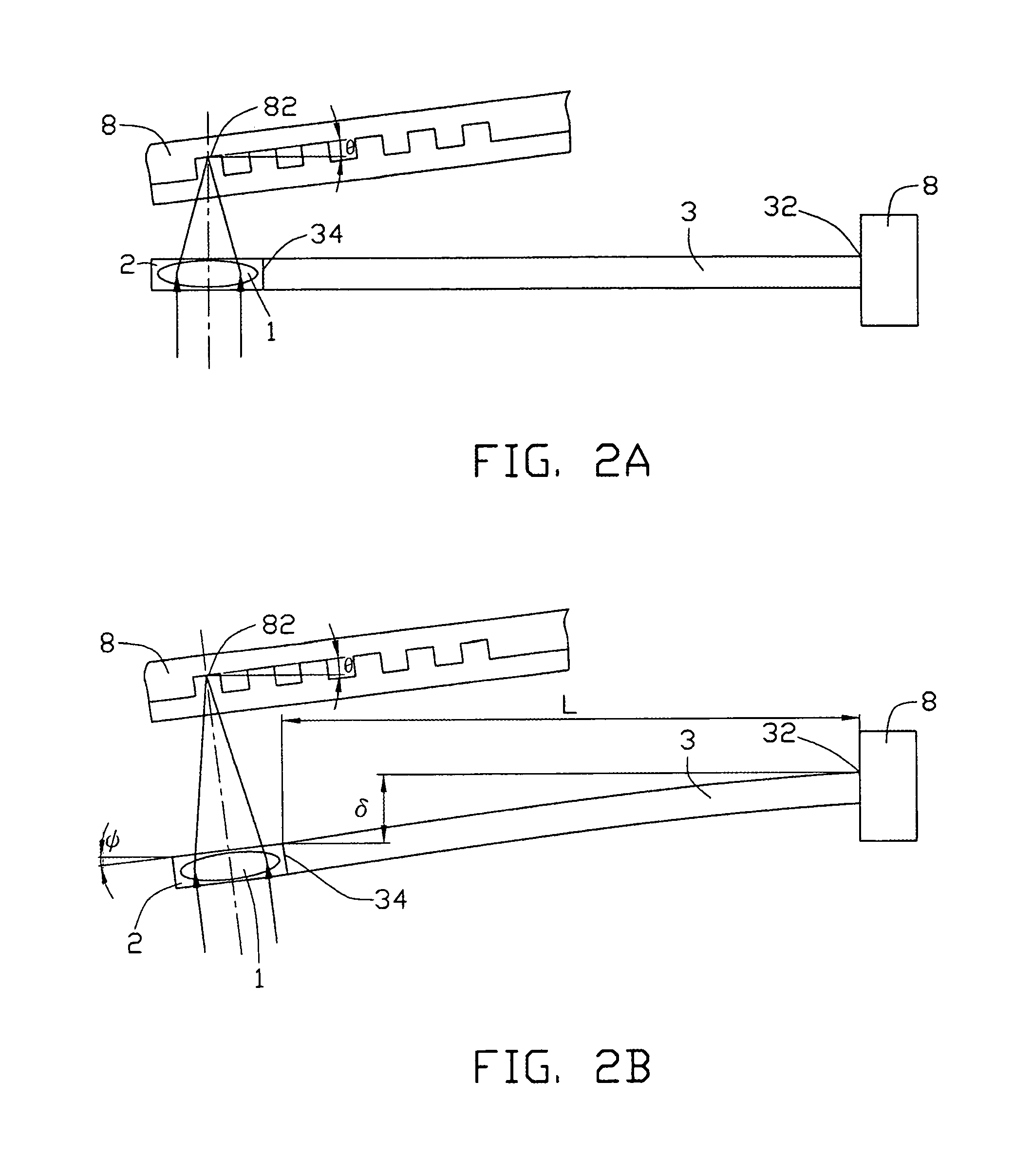
FIELD OF THE INVENTION[0001]The present invention generally relates to an optical pickup device for irradiating a light beam onto a recording medium to read and / or record information from and / or to the recording medium and, more particularly, to an optical pickup device with a tilt adjusting actuator for adjusting an optical axis of a lens to compensate for the tilt of the recording medium.BACKGROUND OF THE INVENTION[0002]An optical disc has received attention as a memory medium that becomes a core in the recent rapid development of multimedia. The optical disc is loaded into an optical disc drive to perform reading / writing of data from / to the optical disc by means of an optical pickup head.[0003]In order to improve the reliability of optical discs, it is necessary to store and reproduce high-quality signals to and from the optical discs. If there is a tilt angle of a recording surface of the optical disc with respect to an optical axis of a lens of the optical pickup head, then an ...

Claims


Application Information

Patent Timeline
Patent Type & Authority Patents(United States)
IPC IPC(8): G11B7/00
CPCG11B7/0956G11B7/082
Inventor CHEN, GA-LANE
Owner HON HAI PRECISION IND CO LTD
Learn More