System and method for providing network route redundancy across layer 2 devices

a technology of layer 2 devices and network routes, applied in data switching networks, frequency-division multiplexes, instruments, etc., can solve problems such as inability inability of vrrp and stp to work together in concert on l2 devices to provide failover recovery, and inability of stp and vrrp to coordinate multiple devices

Inactive Publication Date: 2009-07-07
AVAGO TECH INT SALES PTE LTD
View PDF29 Cites 164 Cited by
  • Summary
  • Abstract
  • Description
  • Claims
  • Application Information

AI Technical Summary

Problems solved by technology

In a switched network, all hosts or end nodes connected to the same physical LAN segment reside in the same broadcast domain, which has the potential of flooding the network with traffic and making it essentially unusable as the network grows.
This condition confuses the forwarding algorithm and allows duplicate frames to be forwarded to the same device, perhaps endlessly.
Unfortunately, VRRP and STP are unable to work together in concert on L2 devices to provide failover recovery while preventing network loops.
STP cannot work with VRRP to coordinate multiple devices in a virtual L2 / L3 device because the two operate independently from one another on different layers of the Open Systems Interconnection (OSI) multilayered communication model.
Proposed solutions to the redundancy problem in massive switched L2 / L3 networks have been unsatisfactory.
Furthermore, the ESRP protocol can only achieve a limited number of redundancy levels (approximately four levels of redundancy) among groups of ESRP switches providing redundancy among each other.
In addition to the foregoing, ESRP lacks any authentication mechanism in order to prevent malicious or fraudulent packets from being received from an intruder and acted upon.

Method used


Image

  • System and method for providing network route redundancy across layer 2 devices
  • System and method for providing network route redundancy across layer 2 devices
  • System and method for providing network route redundancy across layer 2 devices

Examples


Embodiment Construction

[0035]Embodiments of a method, system, and article of manufacture comprising software programs for providing network route redundancy across Layer 2 (L2) and hybrid Layer 2 / Layer 3 (L2 / L3) devices in accordance with the present invention are described with reference to the drawings in FIGS. 1 through 15.

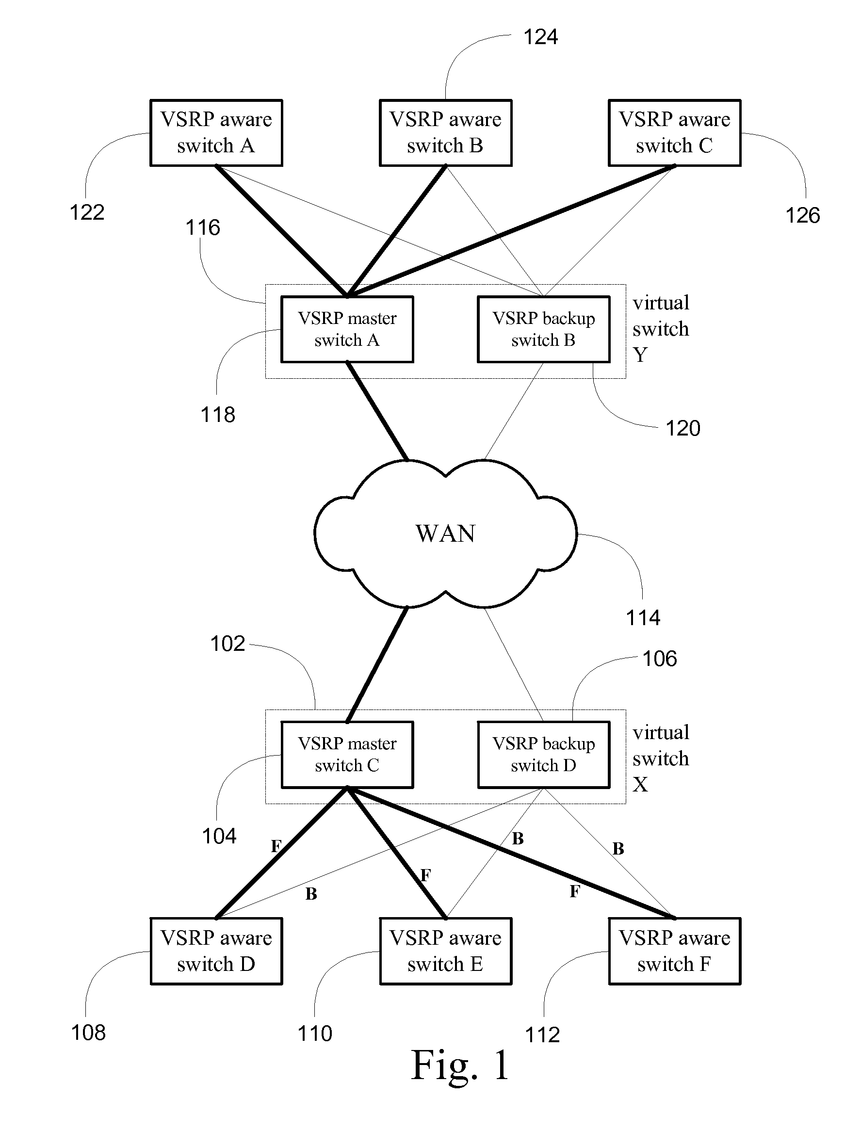
[0036]Turning to FIG. 1, a network topology configured according to one embodiment of the present invention is illustrated. The network topology presented comprises a number of switches 108, 110, 112, 122, 124, 126 performing Layer 2 aggregation and switching functionality. As is explained in greater detail herein, each of these Layer 2 devices 108, 110, 112, 122, 124, 126 is aware of the Virtual Switch Redundancy Protocol or VSRP, described in detail herein, and may thus properly operate with the failover functionality provided by the present invention. An exemplary Layer 2 device 108, 110, 112, 122, 124, 126 is the EdgeIron 4802F switch available from Foundry Networks of San Jose, ...


PUM


Abstract

Systems and methods are described for providing network route redundancy through Layer 2 devices, such as a loop free Layer 2 network having a plurality of switching devices. A virtual switch is coupled to the loop free Layer 2 network, the virtual switch having two or more switches configured to transition between master and backup modes to provide redundant support for the loop free Layer 2 network, the switches communicating their status through use of a plurality of redundancy control packets. The system also includes means for allowing the redundancy control packets to be flooded through the Layer 2 network. The means may include time-to-live data attached to the redundancy control packet which is decremented only when the packets are transferred through devices which are configured to recognize the protocol used in redundancy control packets.

Description

CROSS-REFERENCES TO RELATED APPLICATIONS[0001]The present application claims priority from and is a continuation of U.S. Non-Provisional application Ser. No. 10 / 124,449, filed Apr. 16, 2002, now U.S. Pat. No. 7,209,435, entitled SYSTEM AND METHOD FOR PROVIDING NETWORK ROUTE REDUNDANCY ACROSS LAYER 2 DEVICES, the entire contents of which are incorporated herein by reference for all purposes.[0002]The present application also incorporates herein by reference for all purposes the entire contents of U.S. Non-Provisional application Ser. No. 10 / 090,669, filed Mar. 4, 2002, now U.S. Pat. No. 6,717,922, entitled NETWORK CONFIGURATION PROTOCOL AND METHOD FOR RAPID TRAFFIC RECOVERY AND LOOP AVOIDANCE IN RING TOPOLOGIES.COPYRIGHT NOTICE[0003]A portion of the disclosure of this patent document contains material which is subject to copyright protection. The copyright owner has no objection to the facsimile reproduction by anyone of the patent document or the patent disclosure, as it appears in ...

Claims


Application Information

Patent Timeline
Patent Type & Authority Patents(United States)
IPC IPC(8): H04J1/16H04L12/56H04L45/18H04L45/586H04L69/40
CPCH04L45/18H04L45/32H04L45/586H04L69/40H04L45/76H04L45/00H04L45/48H04L43/0876H04L49/552
Inventor KUO, ANDREW TAI-CHINHSU, IVY PEI-SHANMONCADA-ELIAS, JORDIJALAN, RAJKUMARKAMAT, GURUDEEP
Owner AVAGO TECH INT SALES PTE LTD
Why Eureka
Try Eureka