Method for extracting images of vascular structure and blood flow from image sequences

a technology of vascular structure and image sequence, applied in image enhancement, instruments, applications, etc., can solve the problem of not being able to directly observe changes by the camera, and achieve the effect of suppressing both the non-modulating background and nois

Inactive Publication Date: 2009-07-07
WILLIAMS DARIN S
View PDF11 Cites 45 Cited by
  • Summary
  • Abstract
  • Description
  • Claims
  • Application Information

AI Technical Summary

Benefits of technology

[0027]The fundamental new, unobvious, and unexpected, concept is that periodic biological phenomena and the related anatomy that cannot be seen in imagery using typical means, can nonetheless be made visible in the same imagery by demodulating individual image areas according to the timing of that biological function. In particular, vascular structure and the function of that structure becomes observable when demodulated according to the patient's heart beat.
[0028]Conventional wisdom does not regard such effect as observable. Most typically this is because no one thought about there being an effect to observe (the universal response of everyone that the inventor has queried). On deeper thought, most believe (in the absence of evidence), that the modulation depths due to these phenomena would be considerably below the level of the background clutter. That is, they would be lost in the normal spatial variations across the patient's body. However, experience from a different area of radiometry indicates that this would not be a problem.
[0029]In calibrating the absolute radiometric response of an infra-red sensor in a high background or severe attenuation test-range environment it is typical to use a chopped source. This source may consist of a rotating chopper wheel in front of a conventional black body thermal source. The signal is then measured using a lock-in amplifier or equivalent, suppressing both the non-mo...

Problems solved by technology

The difficulty is that these changes a...

Method used


Image

  • Method for extracting images of vascular structure and blood flow from image sequences
  • Method for extracting images of vascular structure and blood flow from image sequences
  • Method for extracting images of vascular structure and blood flow from image sequences

Examples


embodiment

Preferred Embodiment

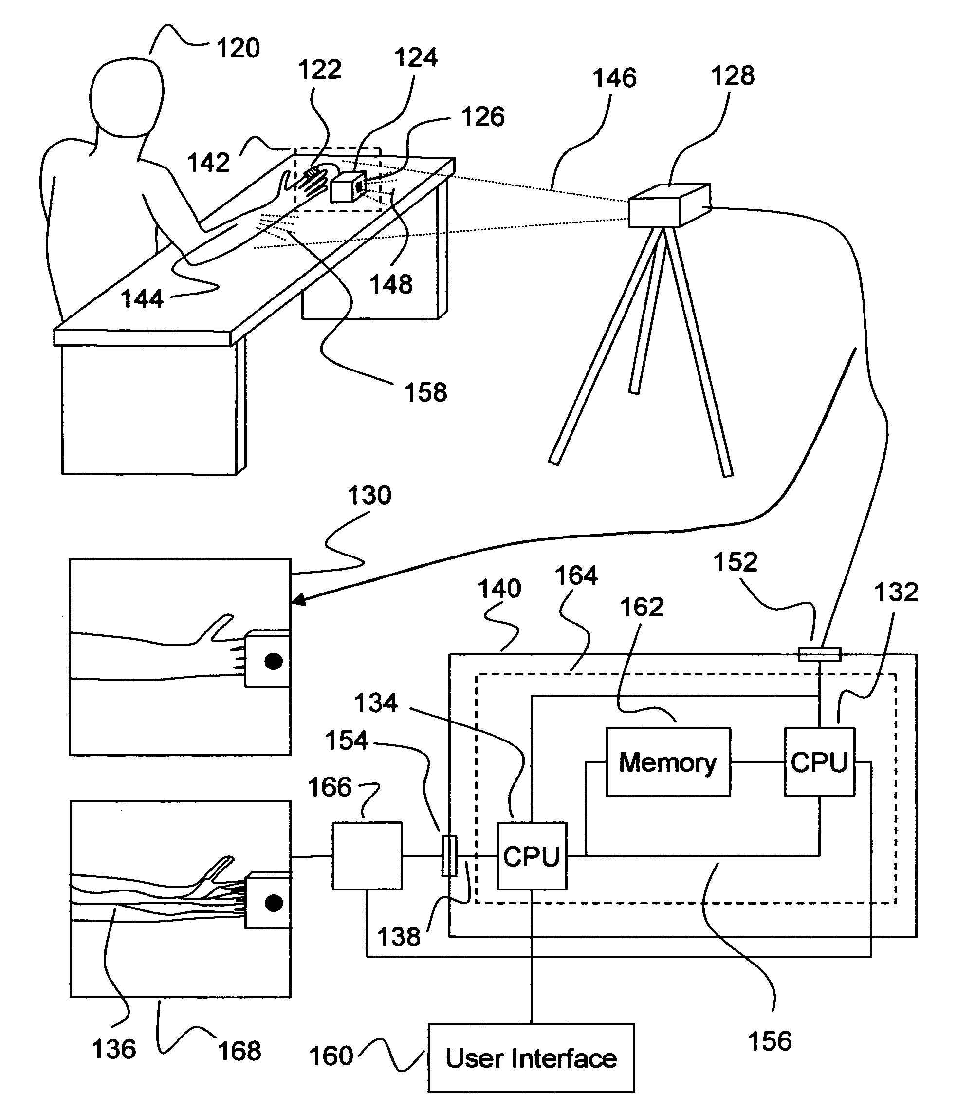
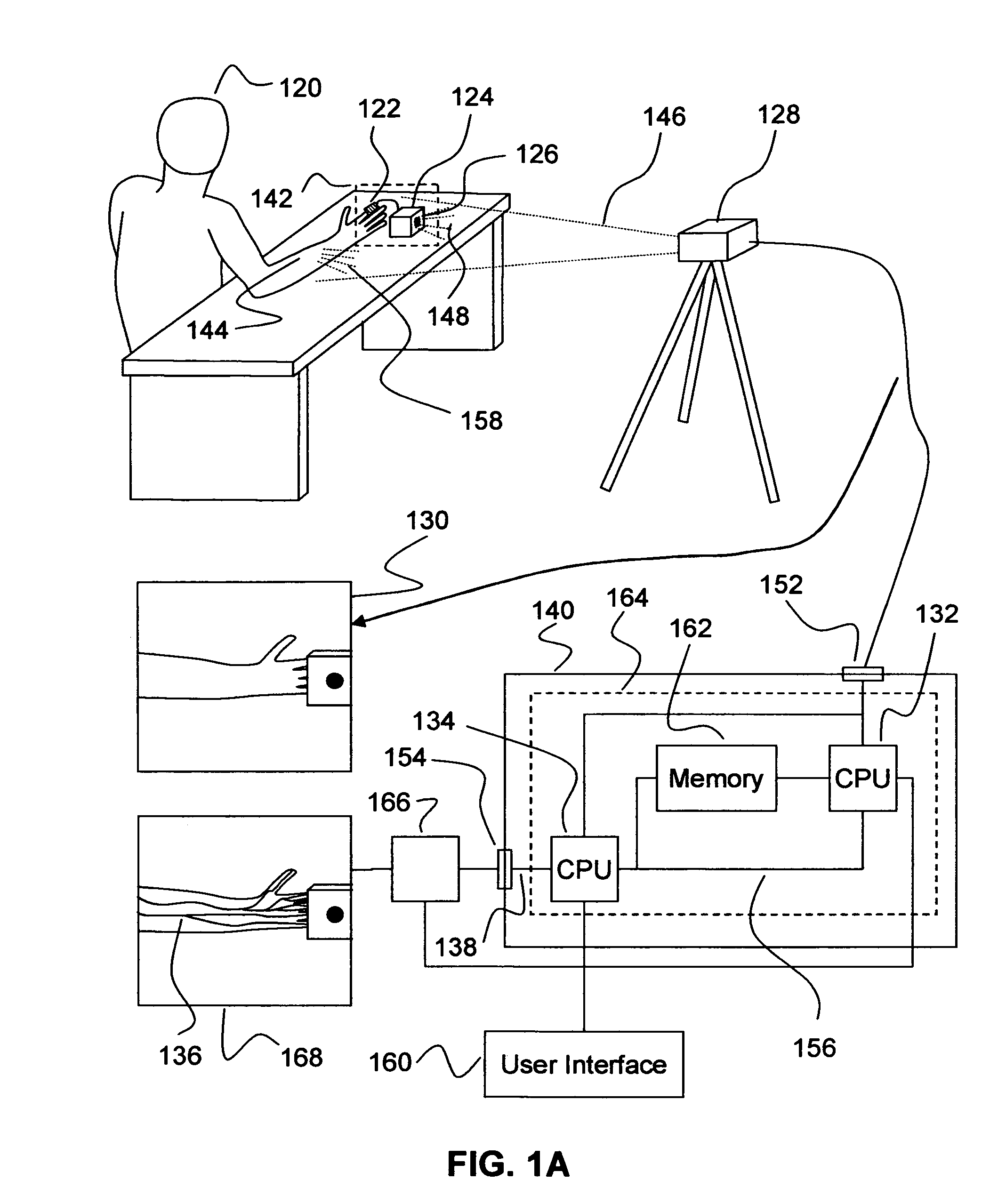
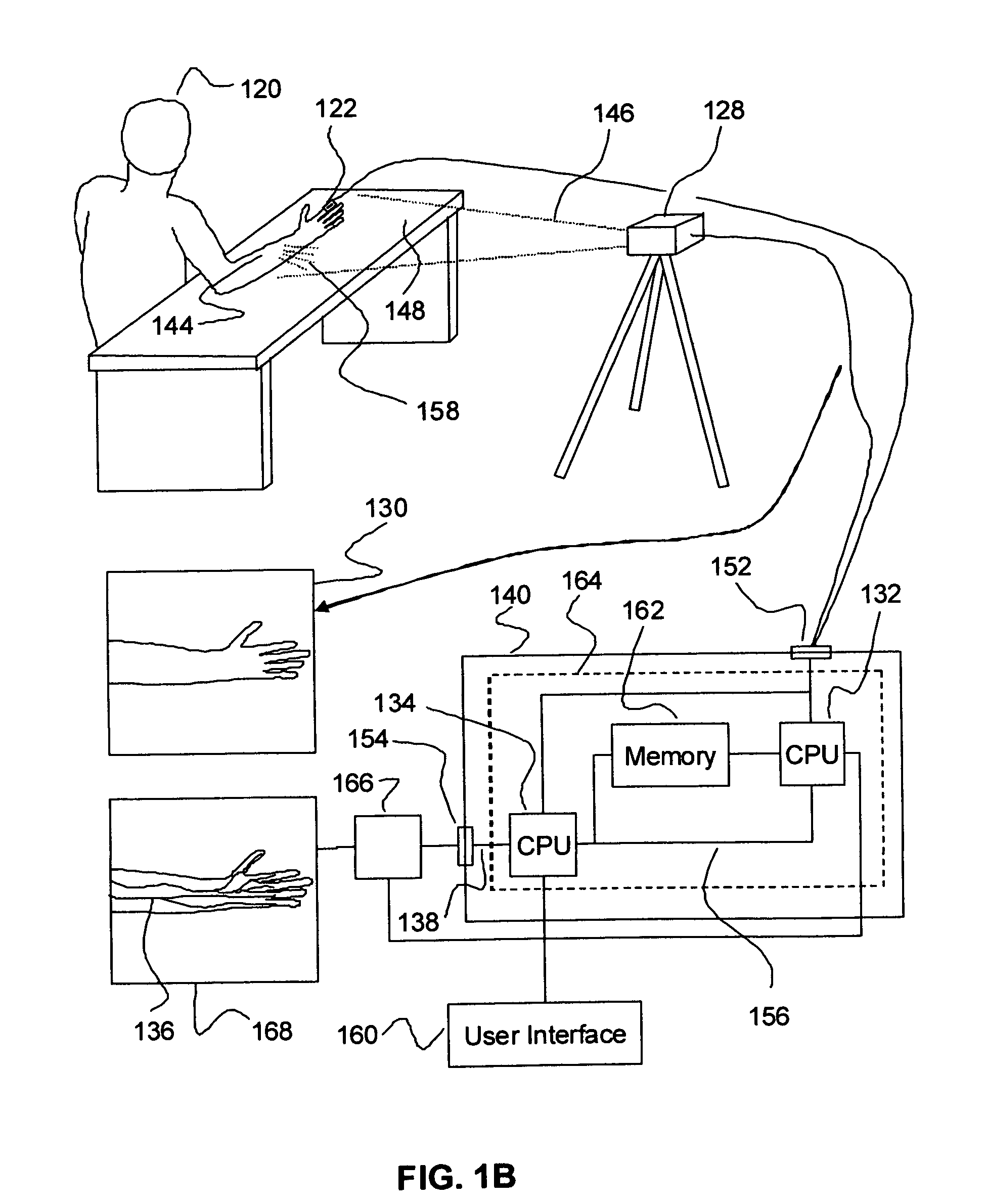
[0214]A living creature or patient 120 (FIG. 1), exhibits some periodic biological function. The objective is to be able to visualize, using imaging equipment or camera 128, subtle changes across the patient that modulate according to rhythm of this function. The difficulty is that these changes are not directly observable by the camera 128. The operations discussed here correct this.

[0215]The remainder of this operational discussion focuses upon the special case where the periodic biological function of interest is the patient's heart beat or pulse, where the pulse is used to highlight vascular structure and to characterize the blood flow through it in novel ways, and where the patient is observed using some form of infra-red camera. This focus is strictly for purposes of illustration and clarity, to avoid unnecessarily cluttering the discussion, and is not intended as restrictive.

[0216]First, the camera 128 is placed so that the area that we wish to observe of ...


PUM


Abstract

Periodic biological functions and their related anatomy that cannot be seen in image sequences using typical means, can nonetheless be made visible by demodulating the image sequence according to the timing of that biological function using the described method. In particular, vascular structure and the function of that structure becomes observable when demodulated according to the patient's heart beat. This method suppresses the effects of thermal variations across the anatomy, and of severe scattering loss from buried tissues, that limit current thermographic (heat imaging) methods. It also measures localized changes in the wave front amplitude, shape, and phase, which are expected to prove useful for disease diagnosis and biometry.

Description

[0001]This application claims the benefit of provisional patent application No. 60 / 644,707 filed Jan. 18, 2005.STATEMENT REGARDING FEDERALLY FUNDED R&D[0002]No federal R&D funds were used in the development of this invention.REFERENCE TO LIST OR CD APPENDIX[0003]Not applicable.BACKGROUND OF THE INVENTION[0004]1. Field of Invention[0005]This invention relates to the measurement of biological functions and the related anatomy.[0006]2. Description of Prior Art[0007]Doctors always need better tools for visualizing anatomy and evidences of disease. X-Ray, CT-scans (computer tomographic), MRI (magnetic resonance imaging), and thermography (infra read thermal imaging) serve different niches of this need. Each brings different capabilities. This discussion begins with thermography, as the most relevant of the prior art to the current invention, and then reviews the limited existing applications of time-series imagery in other types of imaging.[0008]Thermographic mammography has drawn intere...

Claims


Application Information

Patent Timeline
IPC IPC(8): A61B5/05A61B6/00
CPCA61B5/0059A61B5/015A61B5/489G06T7/0012G06T7/2033G06T2207/10048G06T2207/30104G06T2207/10016A61B5/0255G06T7/246
Inventor WILLIAMS, DARIN S
Owner WILLIAMS DARIN S
Why Eureka
Try Eureka