IDC tool with extended reach

a technology of extending reach and tools, applied in the direction of wrenches, other manufacturing equipment/tools, manufacturing tools, etc., can solve the problems of increasing crowded connections and difficult work

Active Publication Date: 2007-07-26
SULLSTAR TECH
View PDF29 Cites 0 Cited by
  • Summary
  • Abstract
  • Description
  • Claims
  • Application Information

AI Technical Summary

Problems solved by technology

As the connector board technology has progressed the connectors have become more and more crowded and have become difficult to work with.

Method used


Image

  • IDC tool with extended reach
  • IDC tool with extended reach
  • IDC tool with extended reach

Examples


Embodiment Construction

FIGS. 1, 2a, and 2b

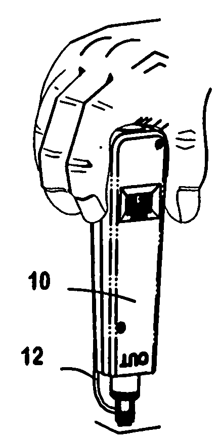
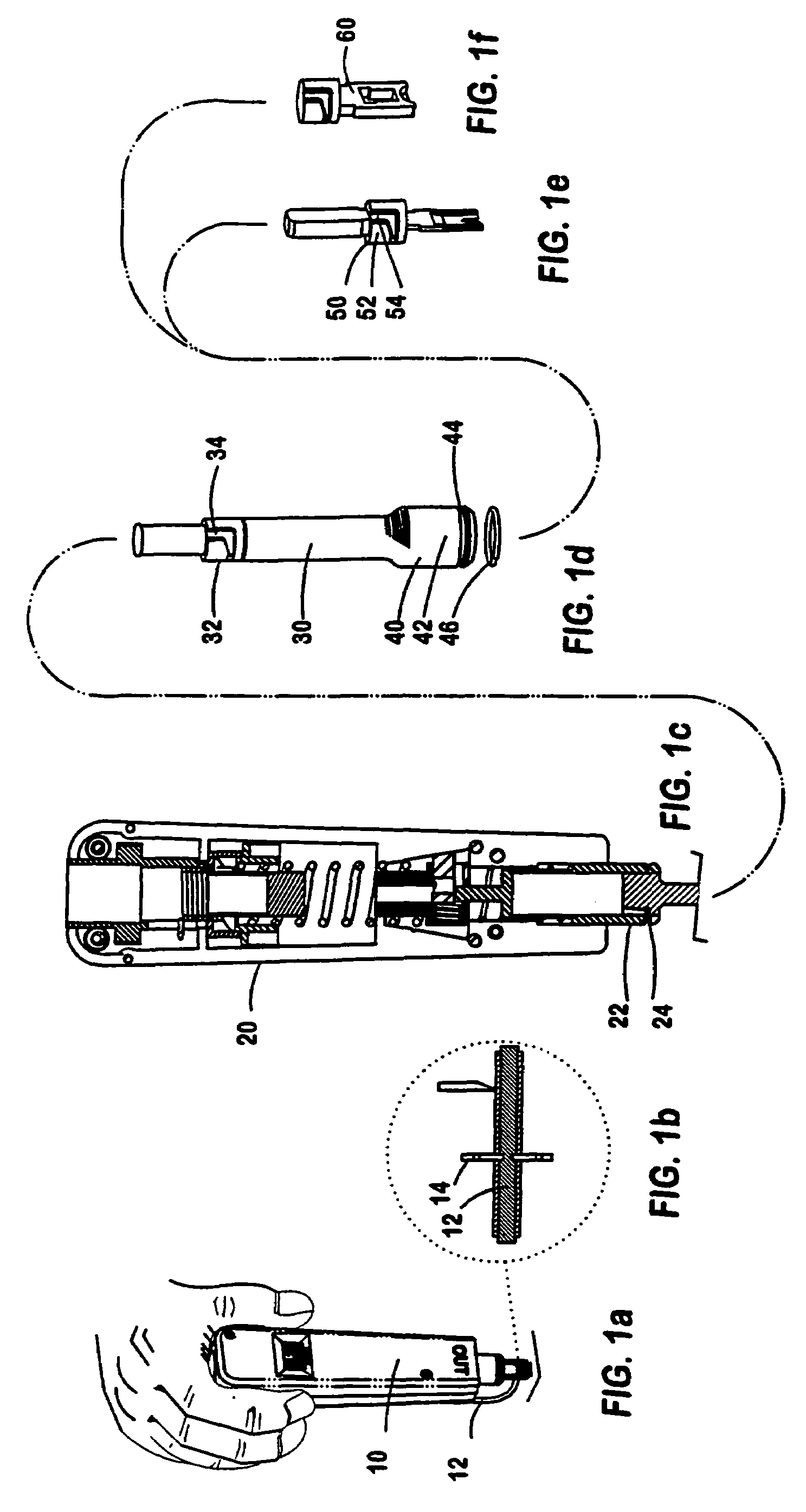
[0013]As shown in the drawings, a tool system 10 for inserting an insulated wire 12 into the knife blades 14 of an Insulation Displacement Connector (IDC) includes a punch-down tool 20 whose effective length is extended by use of my novel extension device 30. A wire end insert tool 50 is then securely locked in the lower end of the extension device. A wire end insert tool of the 110 type is shown, for example, in my Pat. No. 7,096,564.

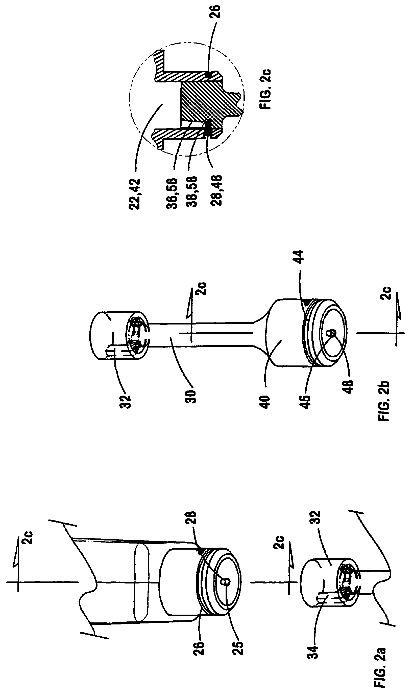
[0014]More specifically, the punch-down tool 20 has a hollow cylindrical lower driving end 22 with a circumferential groove 24 extending about its outer surface. At one point in groove 24 a single hole 25 is formed through the groove wall. A locking spring 26 is disposed within the circumferential groove 24 and extends about most, but not all, of its circumferential length. The spring 26 has an inturned end 28 which extends through the radial hole 25 in order to perform a locking function.

[0015]The tool extension device 30 is of elo...


PUM

PropertyMeasurementUnit
lengthaaaaaaaaaa
circumferenceaaaaaaaaaa
driving forceaaaaaaaaaa

Abstract

A tool system for inserting an insulated wire between knife blades of an insulation displacement type electrical connector, in which the reach of the tool is expanded by use of a an extension member easily inserted between a punch down tool and a wire end insert tool.

Description

PRIORITY CLAIM[0001]This application claims priority of my Provisional Application No. 60 / 761,825 filed Jan. 26, 2006.FIELD OF THE INVENTION[0002]The field of this invention is tools for the electrical communications industry.BACKGROUND OF THE INVENTION[0003]When installing insulated electrical wires into Insulation Displacement type electrical Connectors (IDCs) it has been a standard practice to use a wire insertion tool blade for pushing the insulated wire down between the pair of knives of the connector. My U.S. Pat. No. 7,096,564 issued Aug. 29, 2006 shows the manner in which the tool blade controls the insertion of an insulated wire into an insulation displacement type electrical connector. The knives then cut through the insulation to make an electrical connection. The wire insert tool blade typically also includes a cutting edge for cutting off a protruding end portion of the wire after it has been inserted, if the wire is to then become electrically terminated at that partic...

Claims


Application Information

Patent Timeline
Patent Type & Authority Applications(United States)
IPC IPC(8): B23P23/00
CPCH01R43/015Y10T29/5151Y10T29/5193Y10T29/53222Y10T29/53257
Inventor SULLIVAN, ROBERT W.
Owner SULLSTAR TECH
Why Eureka
Try Eureka