
Broadcasting receiver having operation mode selection function

Inactive Publication Date: 2009-07-07
FUNAI ELECTRIC CO LTD
View PDF16 Cites 6 Cited by
  • Summary
  • Abstract
  • Description
  • Claims
  • Application Information

AI Technical Summary

Benefits of technology

[0007]The present invention is made to solve the above-mentioned problems and it is an object of the present invention to provide a broadcasting receiver that the operation mode for each of a plurality of users can be set and selected by simple operations, when the receiver is owned by a plurality of users, so that the operation mode for each user thereof can be chosen without confusing.
[0009]Thus, by using the numeral inputting key to enter a predetermined selection number, it is possible to select an operation mode which is set for each user including displaying of information of a channel for viewing. With this, therefore, the operation mode can be selected easily. Also, since the existing numeral inputting key is used to enter an operation mode selection, no new hardware needs to be assigned, thus suppressing down the manufacturing costs. Also, the selection number entered when the operation mode is selected can be assigned a number different from the channel number so that the user can discriminate the selection number and the channel number in operation. Further, this operation can be carried out only by using the numeral inputting key without displaying the menu display, so that it is unnecessary to interrupt the display of images output on the display device. Therefore, the user can select the operation mode while enjoying viewing the images simultaneously.

Problems solved by technology

Further, this operation can be carried out only by using the numeral inputting key without displaying the menu display, so that it is unnecessary to interrupt the display of images output on the display device.

Method used


Image

  • Broadcasting receiver having operation mode selection function
  • Broadcasting receiver having operation mode selection function
  • Broadcasting receiver having operation mode selection function

Examples


first embodiment

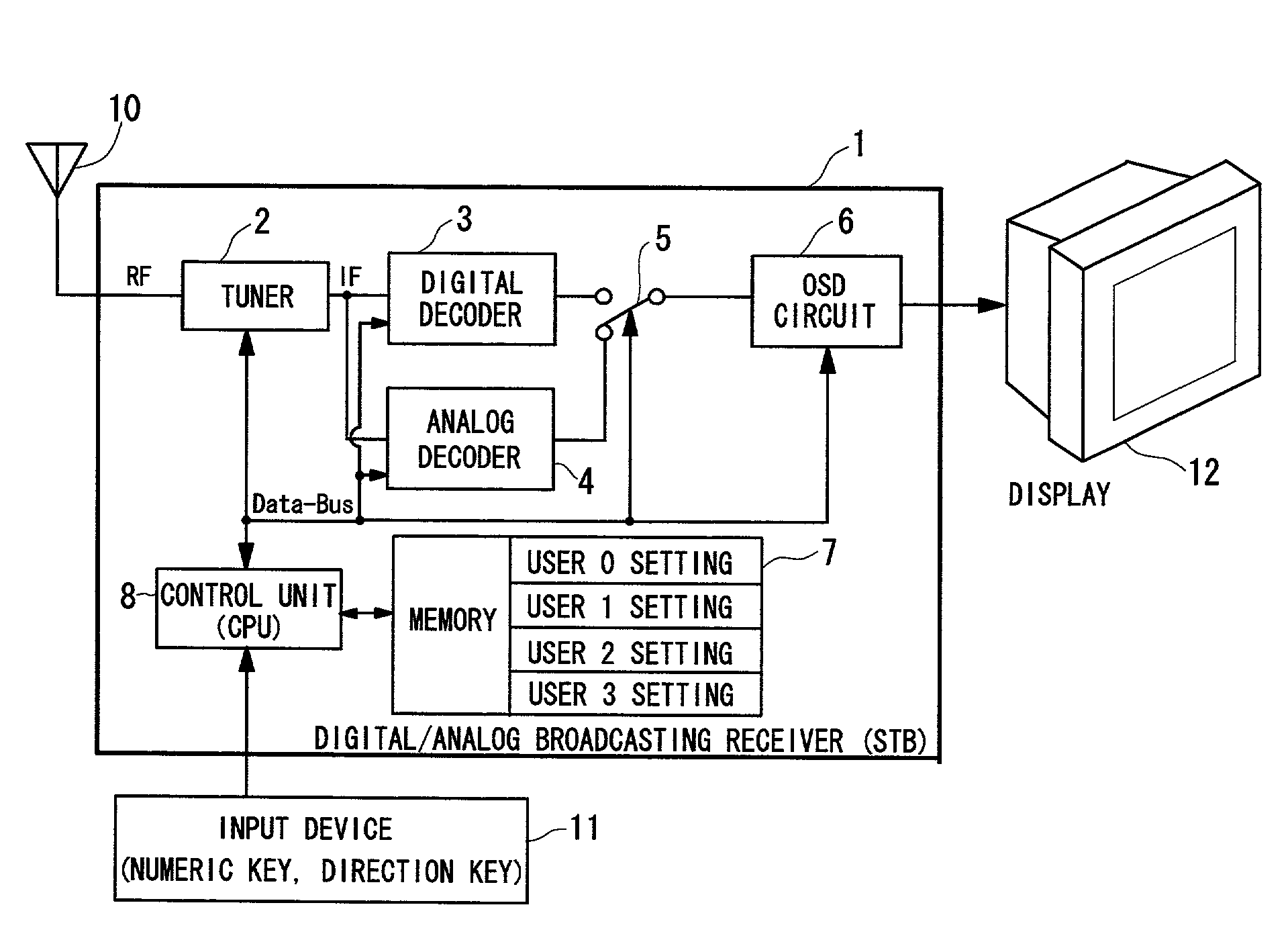
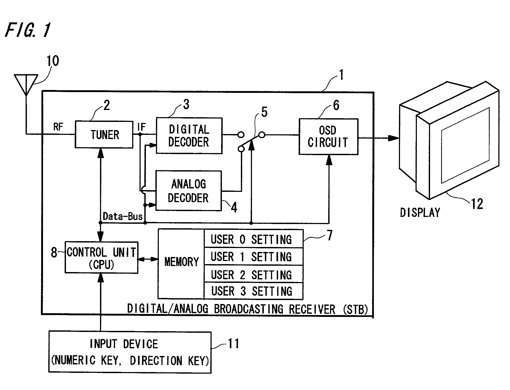
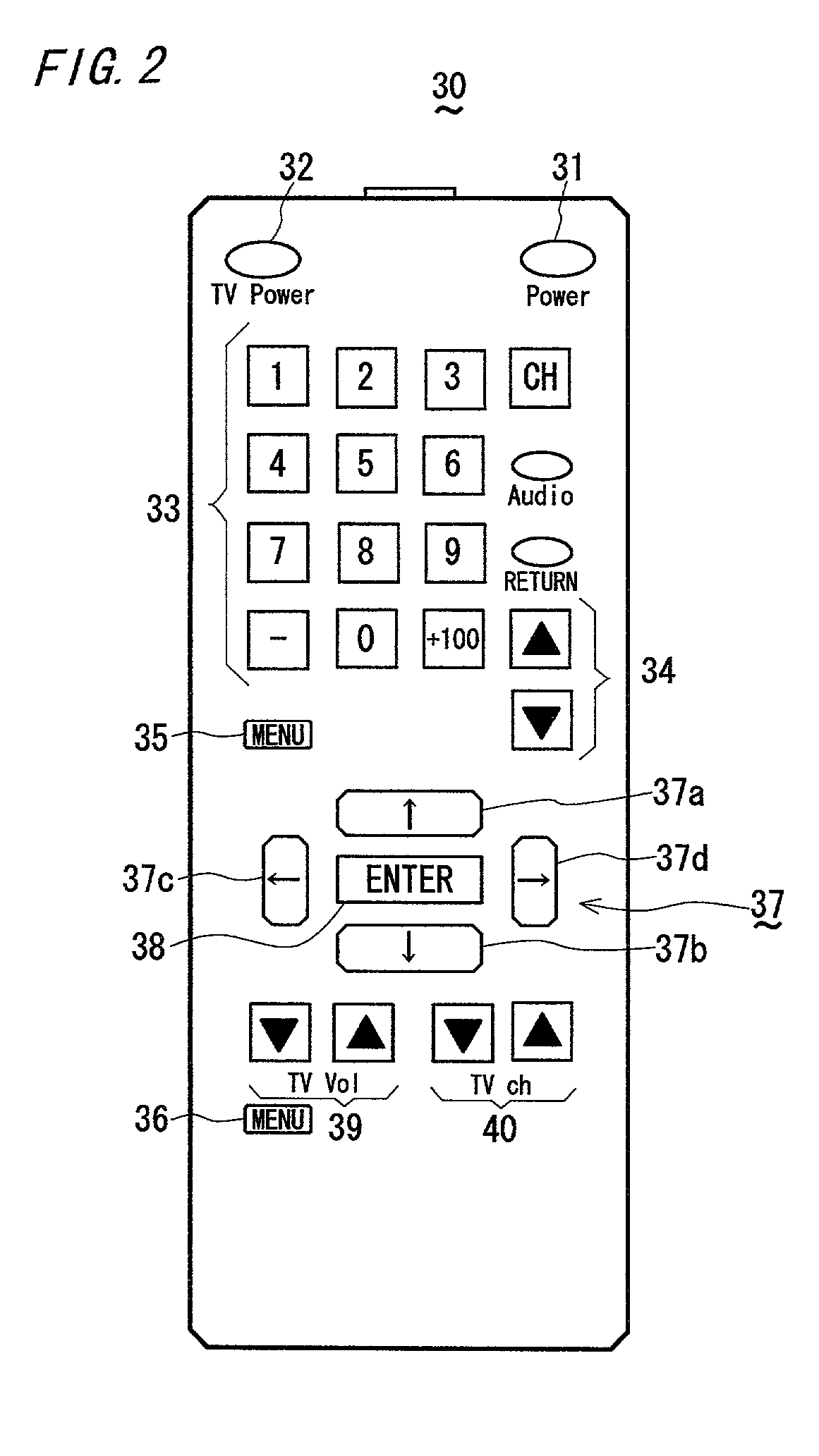
[0024]The following will describe a digital / analog broadcasting receiver related to one embodiment of the invention with reference to the drawings. FIG. 1 is a block diagram of the digital / analog broadcasting receiver. The receiver 1 is a set top box (STB) that receives at an antenna 10 an encoded radio-frequency (RF) digital / analog broadcasting signal originated from a TV broadcasting station to then display a list of the channel information which can be received by a display device 12 for displaying on a display an image signal contained in the broadcasting signal corresponding to operations for channel information display by the user by use of the body button or an input device 11 such as a later-described remote controller 30 shown in FIG. 2.

[0025]The receiver 1 comprises a tuner 2 for receiving a digital / analog broadcasting signal which is present in a frequency band corresponding to a desired channel, a digital decoder 3 and an analog decoder 4 for decoding the digital / analog ...

second embodiment

[0040]The following will a digital / analog broadcasting receiver according to another embodiment of the invention. The configuration of the receiver shown in FIG. 1, the configuration of the remote controller shown in FIG. 2, the user setting display shown in FIG. 3, and the OSD display shown in FIGS. 4-6 are the same as those by the first embodiment and so their explanation is omitted to describe only the switch-over of the operation mode by selection of the user setting. As mentioned above, the user can operate the remote controller 30 beforehand to set his own preferential operation mode of the receiver 1 and then make a user setting. Then, he assigns a desired one of the direction keys 37 to this user setting and stores it in the memory 7. If the user presses any one of the direction keys 37 with the menu key 35 held down, the control unit 8 refers to the memory 7 to select a user setting assigned that one of the direction keys 37. Note here that when the menu key 35 is pressed a...

third embodiment

[0043]The following will describe a digital / analog broadcasting receiver according to a third embodiment of the invention. The configuration of the receiver shown in FIG. 1, the configuration of the remote controller shown in FIG. 2, the user setting display shown in FIG. 3, and the OSD display shown in FIGS. 4-6 are the same as those by the first embodiment and so their explanation is omitted to describe only the switch-over of the operation mode by selection of the user setting. As mentioned above, the user can operate the remote controller 30 beforehand to set his own preferential operation mode of the receiver 1 and then make a user setting. Then, he assigns a desired one of the numeral keys to this user setting and stores it in the memory 7. This selection number is adapted to take on a numeral of “0” through “9” so as to correspond to the keys on the numeric key 33 on the remote controller 30. When the user holds down any key on the numeric key 33 for at least a predetermined ...


PUM


Abstract

In a broadcasting receiver having a function to set and select an operation mode of the receiver for each user based on input by a plurality of users, the operation mode is selected for each user to make a user setting and stored in a memory in correlation with a predetermined input pattern of an operation key. When having received a user's input in the predetermined pattern, the receiver refers to the memory to select a user setting that corresponds to this input pattern, thus switching the operation mode. It is thus possible to identify the operation mode for each user in use by simple operations.

Description

BACKGROUND OF THE INVENTION[0001]The present invention relates to a digital / analog broadcasting receiver having a function to select a user setting which defines the operation mode of this receiver for each of a plurality of users.[0002]There has conventionally been such a broadcasting receiver that automatically sweeps tuner's reception frequencies to thereby store frequencies of receivable broadcasting waves in a preset memory (see, for example, Japanese Unexamined Patent Publication No. 8-97682). Also, there is such a broadcasting receiver that uses a PLL (Phase Lock Loop) frequency synthesizer to automatically sweep tuner's reception frequencies to thereby detect receivable frequencies and then store them in first memory sequentially and also to detect the receivable frequencies by manual tuning and then store them in second memory (see, for example, Japanese Unexamined Utility Model Publication No. 1-91330).[0003]Also, there is such a broadcasting receiver for receiving a chara...

Claims


Application Information

Patent Timeline
Patent Type & Authority Patents(United States)
IPC IPC(8): H04N5/445H04H20/00H04H40/18H04H60/09H04H60/45H04H60/65H04N5/00H04N5/44H04N5/50H04N7/025H04N7/03H04N7/035
CPCH04H40/18H04H60/09H04N21/4623H04H60/65H04N21/4405H04H60/45
Inventor TAKAGI, TOSHIHIROYAMAMOTO, MANABUINUI, YASUHIROKATAYAMA, TAKAHIRONISHIDA, YUSUKE
Owner FUNAI ELECTRIC CO LTD
Learn More