Abutment module

a technology of abutment and abutment member, which is applied in the direction of conveyors, feeding apparatus, precision positioning equipment, etc., can solve problems such as substantial friction, and achieve the effects of lowering the abutment member, reducing the overall height, and small overall dimensions

Active Publication Date: 2009-07-14
UNTERHUBER SEBASTIAN
View PDF13 Cites 14 Cited by
  • Summary
  • Abstract
  • Description
  • Claims
  • Application Information

AI Technical Summary

Benefits of technology

[0004]One object of the invention is to provide an abutment module of the type initially mentioned which as compared with conventional abutment modules has smaller overall dimensions and in particular a smaller overall height and with which nevertheless the lowering of the abutment member may be performed in a reliable fashion.

Problems solved by technology

Owing to pressing force exerted by the abutting object on the abutment member there is substantial friction on lowering of the abutment member.

Method used


Image

  • Abutment module
  • Abutment module
  • Abutment module

Examples


Embodiment Construction

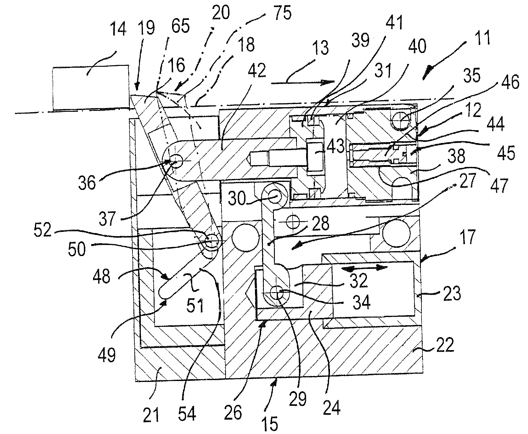
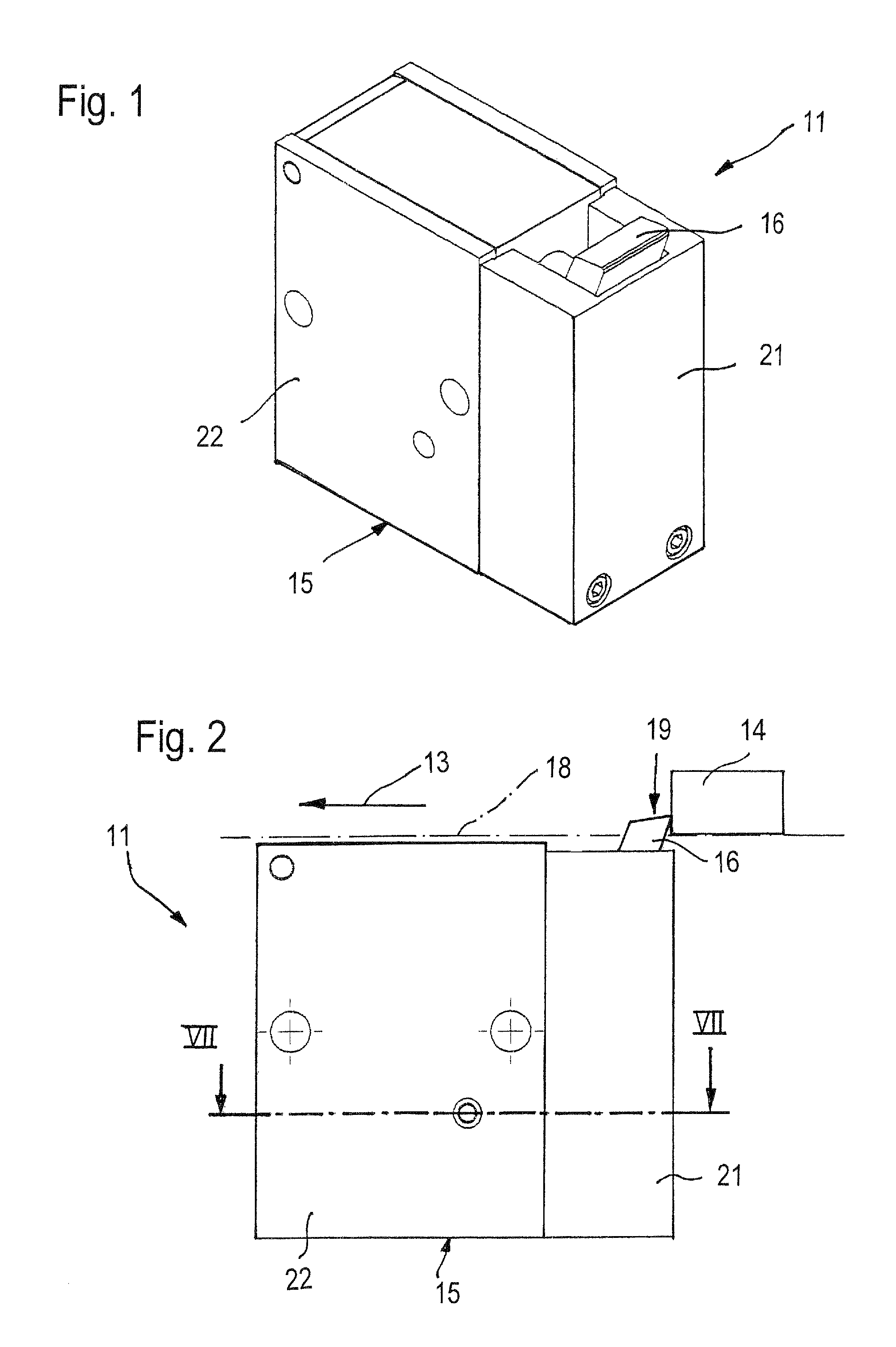
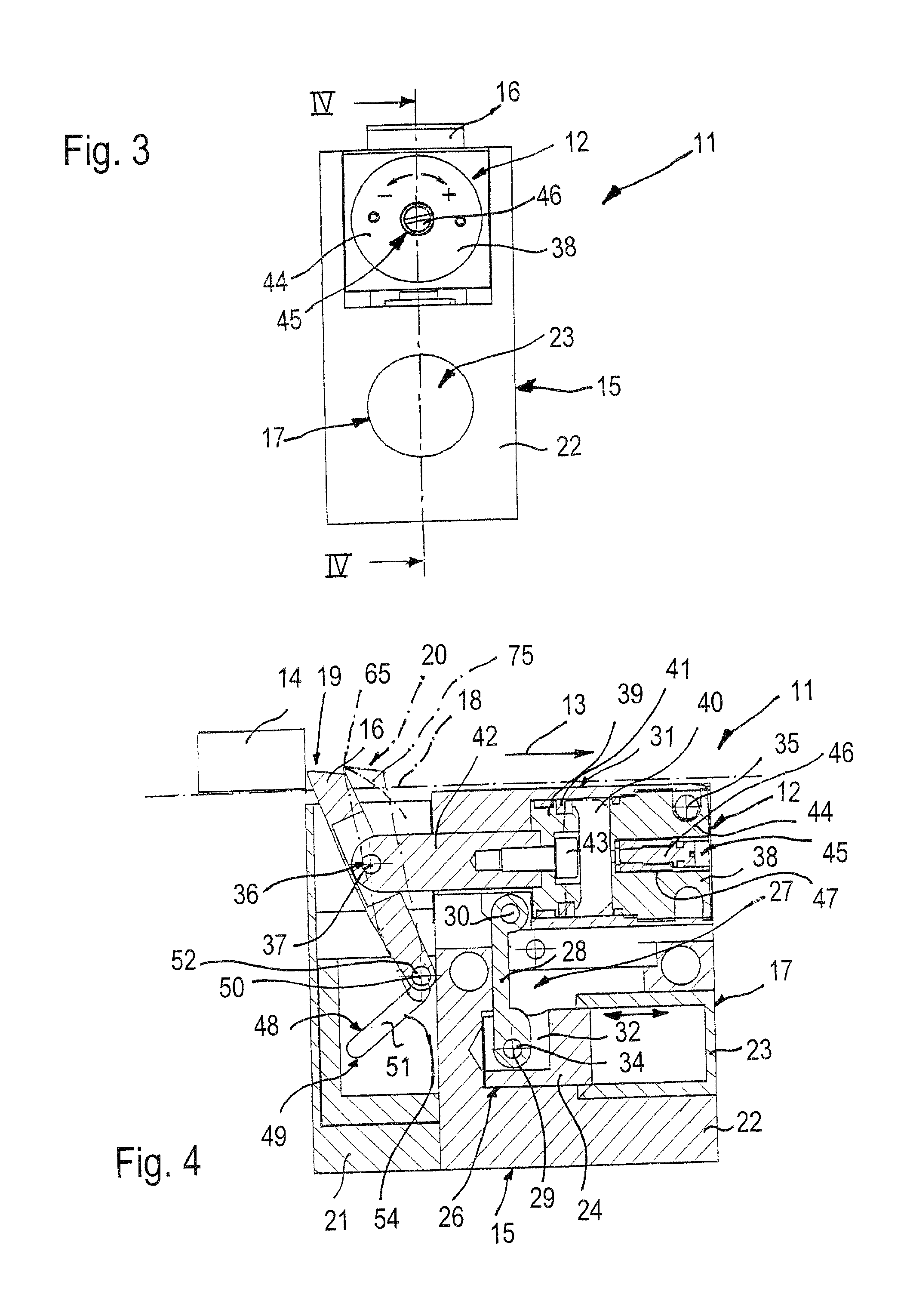
[0029]The FIGS. 1 through 7 show a first working example of the abutment module 11 in accordance with the invention, which in the following will be explained with reference to such a module having a damping means 12. However it is also possible to employ an abutment module without any damping means.

[0030]The abutment module 11 is preferably utilized in automatic processing and conveying means 70 in order to individualize objects 14, such as workpieces or the like, moving in a plane of motion 18 in a working movement direction 13. Following individualizing the objects 14 may then be individually processed, as for example machined, redirected or the like.

[0031]The abutment module 11 possesses a main unit 15, for example in the form of a rectangular block, on which an abutment member 16 is arranged which using a setting member 17 may be shifted out of the plane of motion 18 of the objects 14 and back into it. Furthermore the already mentioned damping means 12 is present, by means of wh...


PUM


Abstract

An abutment module, in particular for automatic processing and conveying systems, comprising an abutment member arranged on a main unit for objects moving in a plane of motion in a current working movement direction, such abutment member being able to be shifted by means of a setting member between an abutment position located in the plane of motion and a release position lying underneath the plane of motion, and the setting member has a drive element for producing a linear drive movement directed in parallelism to the plane of motion, which may be converted by way of a conversion device into an upward and downward movement taking place between the abutment position and the release position of the abutment member.

Description

BACKGROUND OF THE INVENTION[0001]The invention relates to an abutment module, in particular for automatic processing and conveying systems, comprising an abutment member arranged on a main unit for objects moving in a plane of motion in a current working movement direction, such abutment member being able to be shifted by means of a setting member between an abutment position located in the plane of motion and a release position lying underneath the plane of motion.RELATED ART[0002]A abutment module of this type is disclosed in the European patent publication EP 0 484 648. The abutment described therein is able to be shifted by means of a pneumatically operating setting piston out of the path of motion of arriving workpieces and back into the same. For actuation by a compressed air an air connection is provided in the housing, by way of which compressed air may be supplied in a controlled manner. Furthermore the abutment is provided with a damping means so that the movement of the a...

Claims


Application Information

Patent Timeline
Patent Type & Authority Patents(United States)
IPC IPC(8): B65G47/24
CPCB65G47/8823B65G2205/06B23Q5/52B23Q5/26B23Q16/001F16F9/02B23Q2705/12
Inventor UNTERHUBER, SEBASTIAN
Owner UNTERHUBER SEBASTIAN
Why Eureka
Try Eureka