3D camera

a three-dimensional camera and camera body technology, applied in the field of imaging systems, can solve the problems of not capturing the three-dimensional shape or size of objects, the size of the time-of-flight technique is typically limited to about 1 centimeter of resolution, and the existence of photographs typically lack important information regarding objects in images, etc., to facilitate the determination of the amount of variation

Inactive Publication Date: 2009-07-14
NANCHANG O FILM OPTICAL ELECTRONICS TECH CO LTD
View PDF4 Cites 109 Cited by
  • Summary
  • Abstract
  • Description
  • Claims
  • Application Information

AI Technical Summary

Benefits of technology

[0012]According to one aspect of the present invention, a three dimensional image can be formed by using visible light to provide a two dimensional image in a conventional manner and by using time varying invisible light in combination with reference light to provide depth information for objects in the two dimensional image. The time varying invisible light illuminates a scene being photographed. Time varying invisible light that is reflected from the scene is combined with reference light and imaged. Combining the time varying light with the reference light facilitates the determination of the amount of variation in the time varying light. The amount of variation in the time varying light is representative of the depth information.

Problems solved by technology

Yet, existing photographs typically lack important information regarding the objects in an image.
For example, typical contemporary photographs do not capture the three dimensional shape or size of object, because the image is recorded in a flat, two-dimensional fashion.
As a result, time-of-flight techniques typically are limited to about 1 centimeter of resolution and 30 centimeters of measurement range.
In addition, due to the short time the shutter is open, time-of-flight techniques require a very bright light source.
Of course, brighter light sources consume more power and cause concerns regarding eye safety.
In order to measure the short time delays, time-of-flight techniques further require the use of high-speed electronics that are expensive and consume a comparatively great amount of power.
These factors make time-of-flight techniques expensive, bulky, and not well suited for the consumer camera market.
Thus, although such contemporary digital imaging systems have proven generally suitable for their intended purposes, they possess inherent deficiencies which detract from their overall effectiveness and desirability.
Moreover, although the prior art has recognized, to a limited extent, the advantages of three dimensional imaging, the proposed solutions have, to date, been ineffective in providing a satisfactory remedy.

Method used


Image

  • 3D camera
  • 3D camera
  • 3D camera

Examples


Embodiment Construction

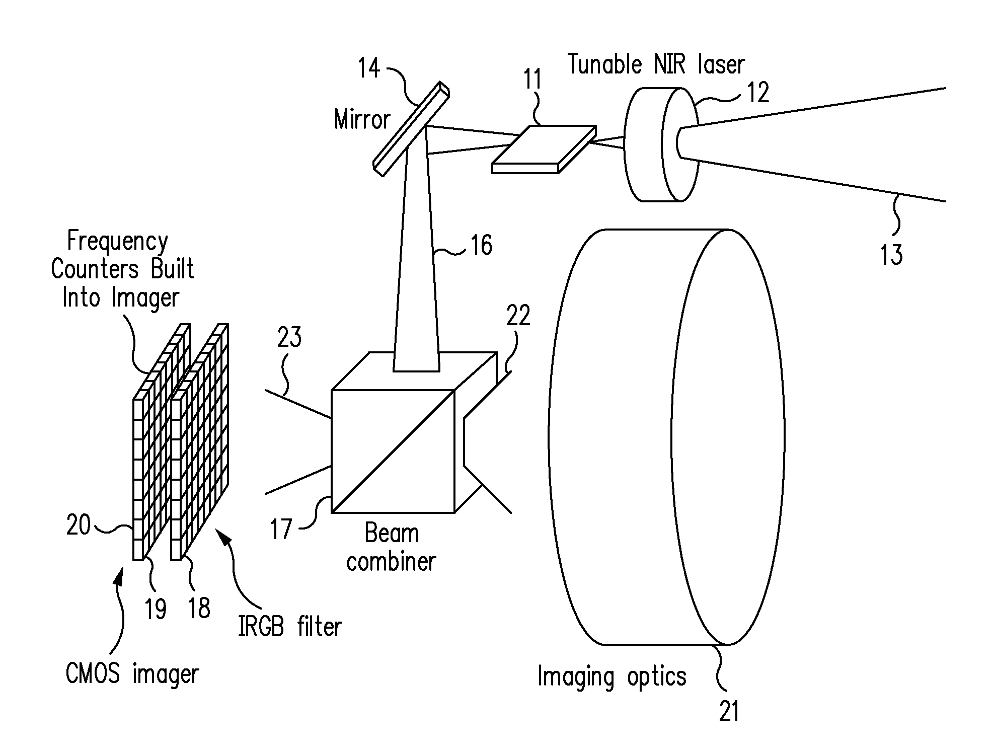
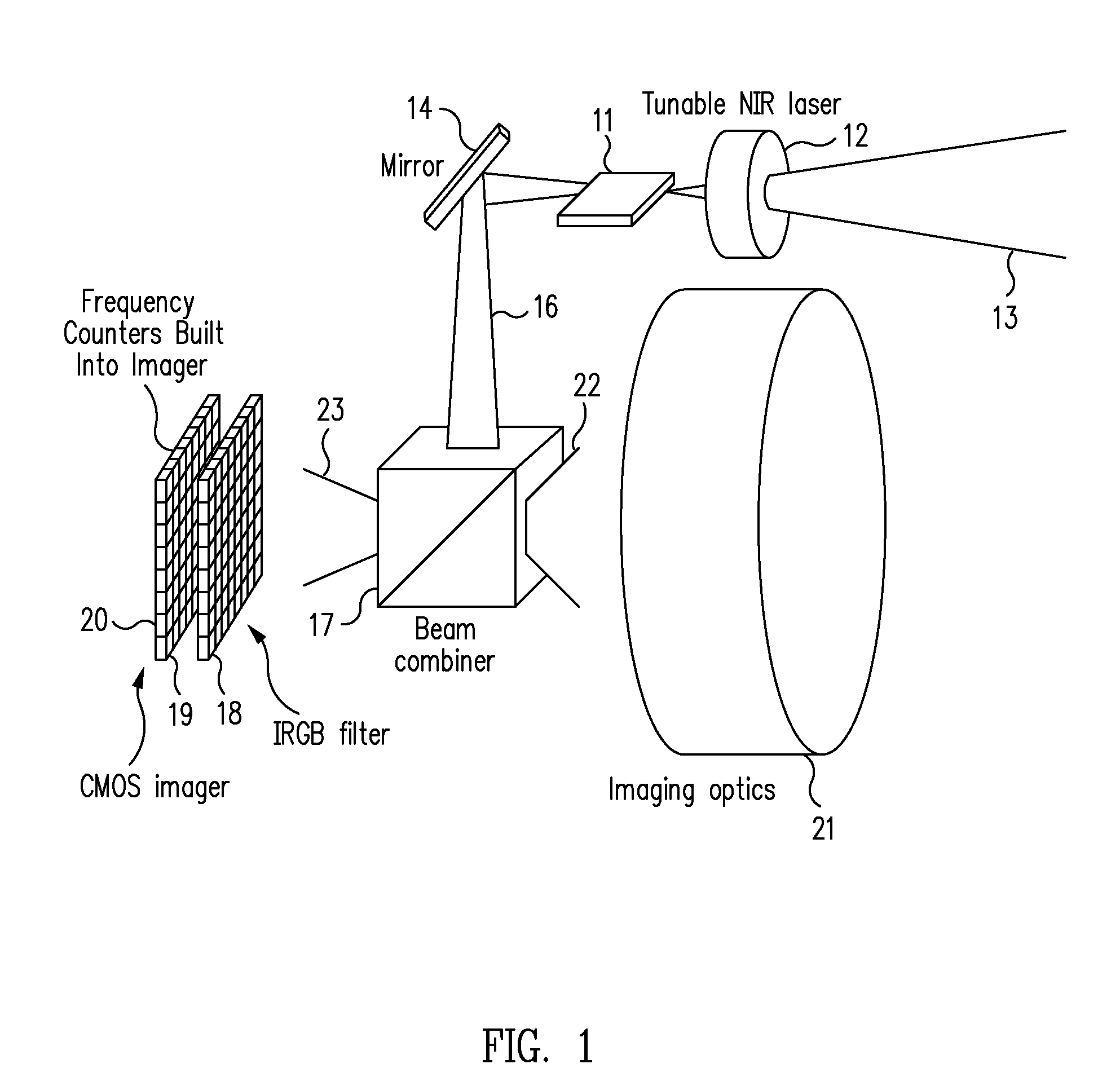
[0023]According to one aspect, the present invention uses a tunable laser and coherent detection to convert the time delay associated with depth information into frequency modulation. As a result, what was a very difficult 6 picosecond resolution time measurement according to contemporary time-of-flight methodology becomes a very simple 1 kilohertz resolution frequency measurement according to one aspect of the present invention.

[0024]More particularly, according to an exemplary embodiment of the present invention, the entire scene being imaged is illuminated with infrared light that is swept in frequency during the exposure period of the imaging process. A traditional two dimensional image is formed on RGB color sub-pixels, substantially according to contemporary methodology. At the same time, an image containing depth information is formed on infrared sub-pixels using the reflected infrared beam. Depth information is obtained by counting the frequency of the reflected infrared lig...


PUM

PropertyMeasurementUnit
round trip timeaaaaaaaaaa
distanceaaaaaaaaaa
time-aaaaaaaaaa

Abstract

Structures and methods are provided for obtaining depth information regarding a scene being imaged. The scene is illuminated with light having a time varying parameter. Light reflected from the scene is received and values for the time varying parameter associated with different portions of the scene are determined.

Description

CROSS-REFERENCE TO RELATED APPLICATIONS[0001]This patent application claims benefit of U.S. Provisional Application No. 60 / 679,486, filed May 10, 2005; and entitled “3D CAMERA”, the entire contents of which are hereby incorporated by reference.TECHNICAL FIELD[0002]The present invention relates generally to imaging systems. The present invention relates more particularly to a three dimensional (3D) camera that uses a tunable laser and coherent detection to provide depth information.BACKGROUND[0003]Digital cameras are well known. As their cost continues to drop, digital cameras grow in popularity. Digital cameras eliminate the need to have film developed. They also greatly reduce the need to have prints made, since digital pictures can be viewed on a computer monitor or the like. Although the initial cost may be higher, digital cameras have greatly reduced the overall cost of photography.[0004]It has been estimated that about 100 billion photographs are taken each year world-wide. The...

Claims


Application Information

Patent Timeline
Patent Type & Authority Patents(United States)
IPC IPC(8): H01L27/00G01C3/08G01J3/50H04N9/083G02F1/01
CPCG01C3/08G01S17/325H04N9/045H04N9/083H04N13/0207H04N13/0253G01S17/89G01J3/0278G01J3/513H04N13/0257H04N13/254H04N13/207H04N13/257G01S17/34G01S17/894H04N25/131H04N23/84H04N25/136H04N9/03
Inventor GUTIERREZ, ROMAN C.
Owner NANCHANG O FILM OPTICAL ELECTRONICS TECH CO LTD
Why Eureka
Try Eureka