Liquid crystal device and electronic apparatus
a technology of electronic equipment and liquid crystal, applied in non-linear optics, instruments, optics, etc., can solve problems such as reducing transmittance or the like, and achieve the effect of reducing the number of domain regions and reducing transmittan
- Summary
- Abstract
- Description
- Claims
- Application Information
AI Technical Summary
Benefits of technology
Problems solved by technology
Method used
Image
Examples
first embodiment
Structure of Liquid Crystal Device
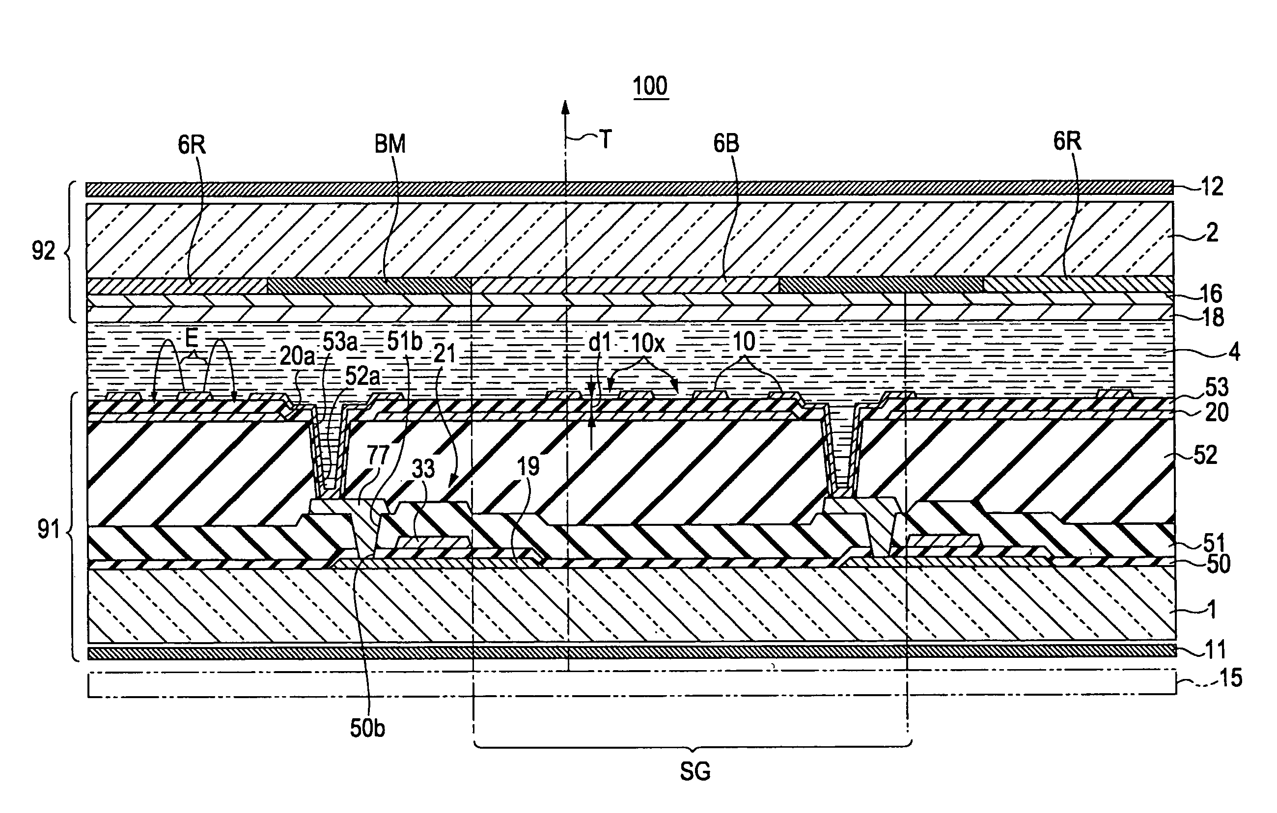
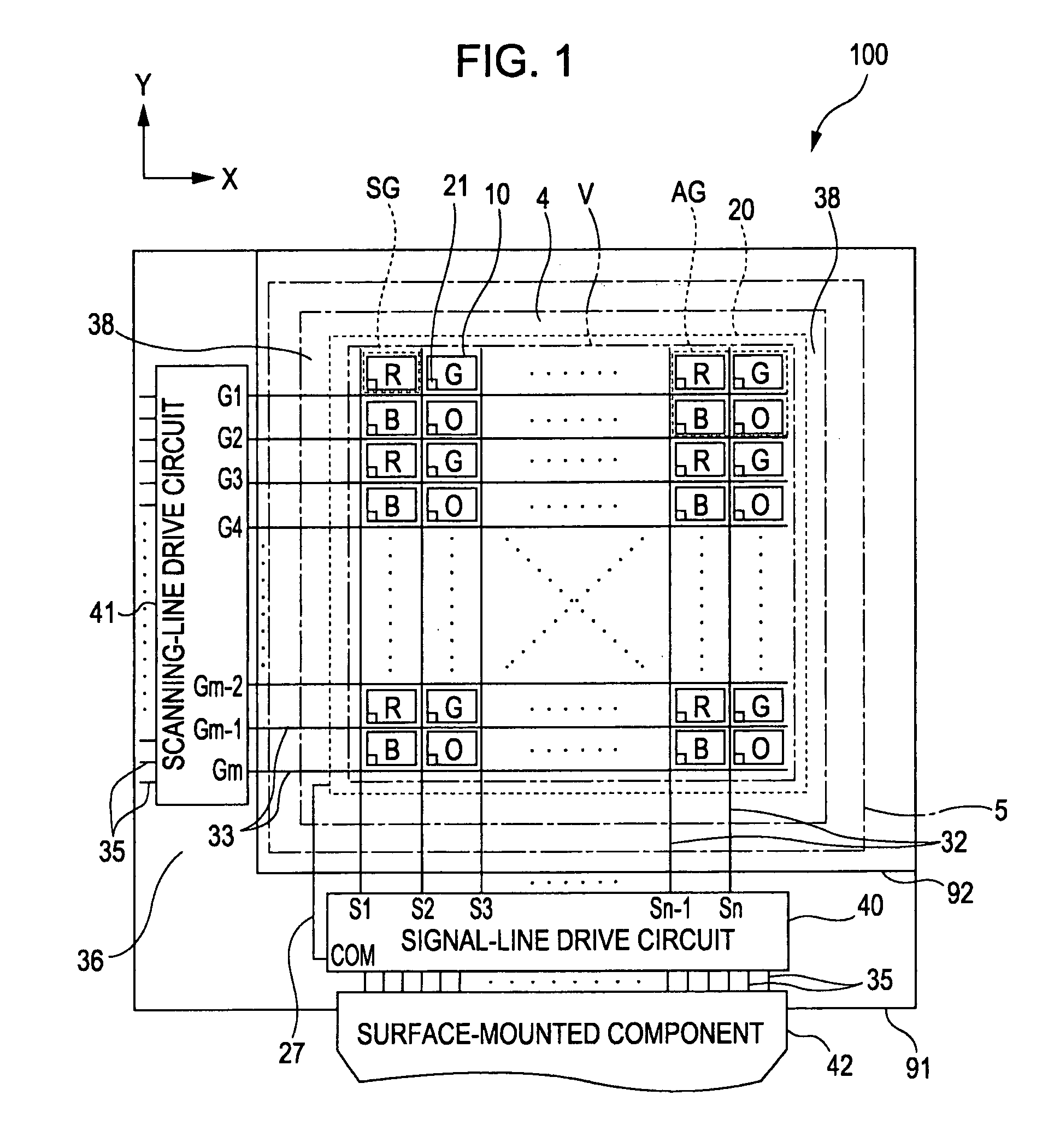
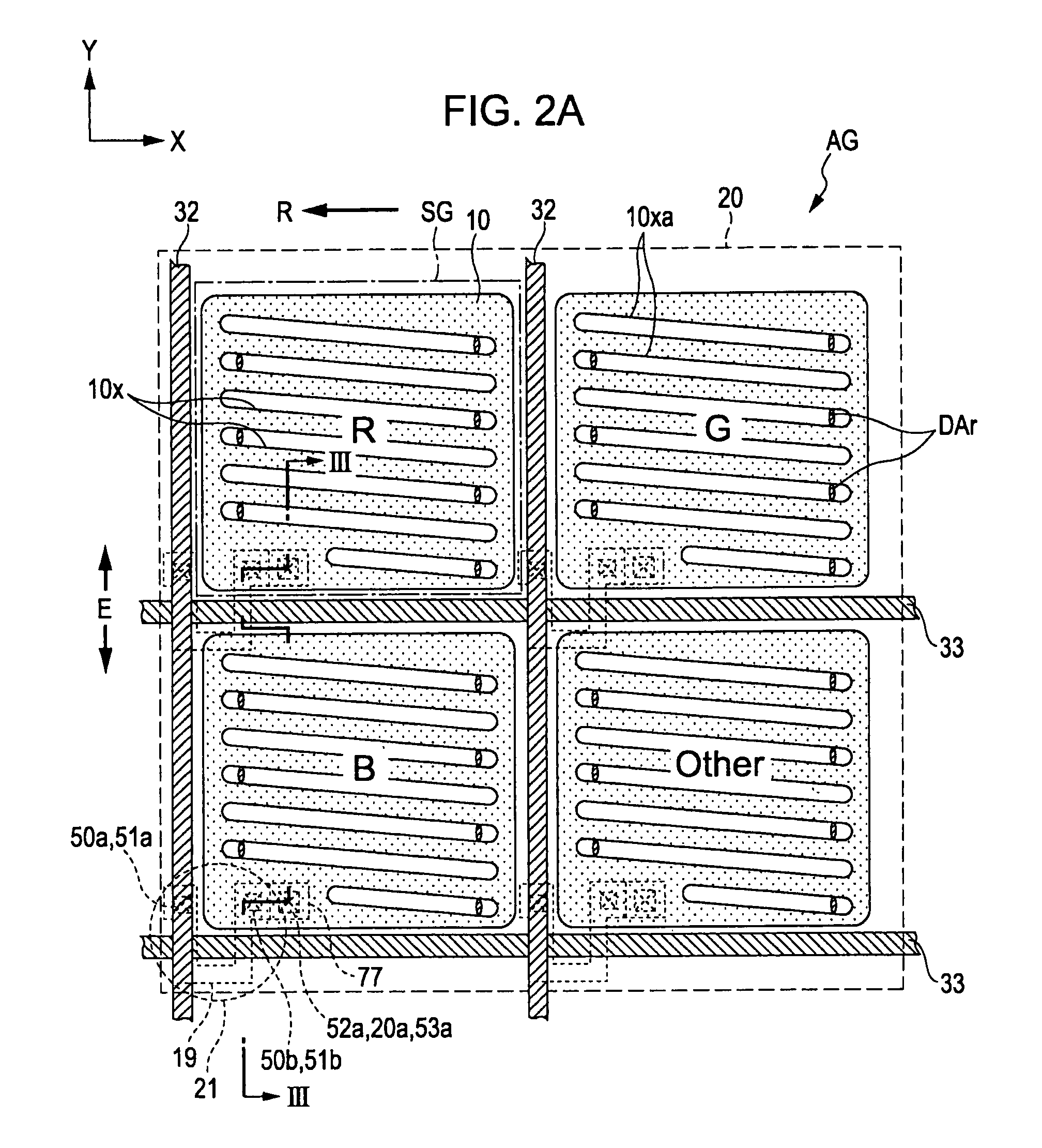
[0045]With reference to FIG. 1 and the like, the structure of a liquid crystal device 100 and the like according to a first embodiment of the invention will be described.
[0046]FIG. 1 is a plan view schematically showing the schematic structure of the liquid crystal device 100 according to the first embodiment of the invention. In FIG. 1, a color filter substrate 92 is placed at the front side when viewed in FIG. 1(near the observer of FIG. 1), and an element substrate 91 is placed at the rear side when viewed in FIG. 1. The vertical direction in FIG. 1 (column direction, which is the direction in which columns extend) is defined as the Y-direction, and the horizontal direction in FIG. 1 (row direction, which is the direction in which rows extend) is defined as the X-direction. In FIG. 1, regions represented by red (R), green (G), blue (B), and an arbitrary color (other, which may be abbreviated as “O”) indicate subpixel regions SG, and a pixel arran...
second embodiment
[0131]With reference to FIGS. 2B and 4, a liquid crystal device 200 according to a second embodiment of the invention will be described.
[0132]FIG. 2B shows the planar structure of one pixel of an element substrate 93 according to the second embodiment. In FIG. 2B, only the minimum components necessary for describing the element substrate 93 are shown. FIG. 4 is a cross-sectional view, taken along the line IV-IV of FIG. 2B, of one subpixel cut at the position across the LTPS TFT 21.
[0133]When the second embodiment is compared with the first embodiment, the main difference is that the positional relationship between the common electrode 20 and the pixel electrodes 10 with respect to the third insulating film 53 serving as a dielectric film on the element substrate is reversed, and the other structural portions are common in both embodiments. Therefore, components common to those in the first embodiment are denoted by the same reference numerals, and descriptions thereof are briefly gi...
PUM
| Property | Measurement | Unit |
|---|---|---|
| thickness d1 | aaaaa | aaaaa |
| thickness d1 | aaaaa | aaaaa |
| wavelength | aaaaa | aaaaa |
Abstract
Description
Claims
Application Information
 - R&D
- Intellectual Property
- Life Sciences
- Materials
- Tech Scout
- Unparalleled Data Quality
- Higher Quality Content
- 60% Fewer Hallucinations
Browse by: Latest US Patents, China's latest patents, Technical Efficacy Thesaurus, Application Domain, Technology Topic, Popular Technical Reports.
© 2025 PatSnap. All rights reserved.Legal|Privacy policy|Modern Slavery Act Transparency Statement|Sitemap|About US| Contact US: help@patsnap.com


