Power converter unit

a power converter and power technology, applied in the direction of electrical apparatus construction details, indirect heat exchangers, lighting and heating apparatus, etc., can solve the problems of difficult assembly, time-consuming process, and affecting the drive circuit, and achieve the effect of high-reliability power converter units

Active Publication Date: 2009-07-14
HITACHI ASTEMO LTD
View PDF10 Cites 77 Cited by
  • Summary
  • Abstract
  • Description
  • Claims
  • Application Information

AI Technical Summary

Benefits of technology

[0007]In view of the foregoing, an object of the present invention is to provide a highly reliable power converter unit. One of the more specific objects is to provide a power converter unit whose heat-resistant performance and noise immunity are raised by adopting a simple structure in which the number of assembling processes can be reduced and by adopting a high-shielding and high heat dissipating structure in the drive circuit board.
[0011]According to the present invention, a highly reliable power converter unit can be provided.

Problems solved by technology

Since the power semiconductor device generate a lot of heat by switching operation, the drive circuit tends to be affected by the heat generated by the power semiconductor devices.
Therefore, there are required time consuming processes such as a curing time for the adhesive.
Therefore, it is necessary to carry out wiring between the drive circuit board and the power semiconductor device by using an additional member, such as a flexible substrate etc., making the assembly difficult.
Therefore, the drive circuit board on the drive circuit is easily be influenced by the switching noise of the power semiconductor device, causing a problem in noise immunity.

Method used


Image

  • Power converter unit
  • Power converter unit
  • Power converter unit

Examples


example 1

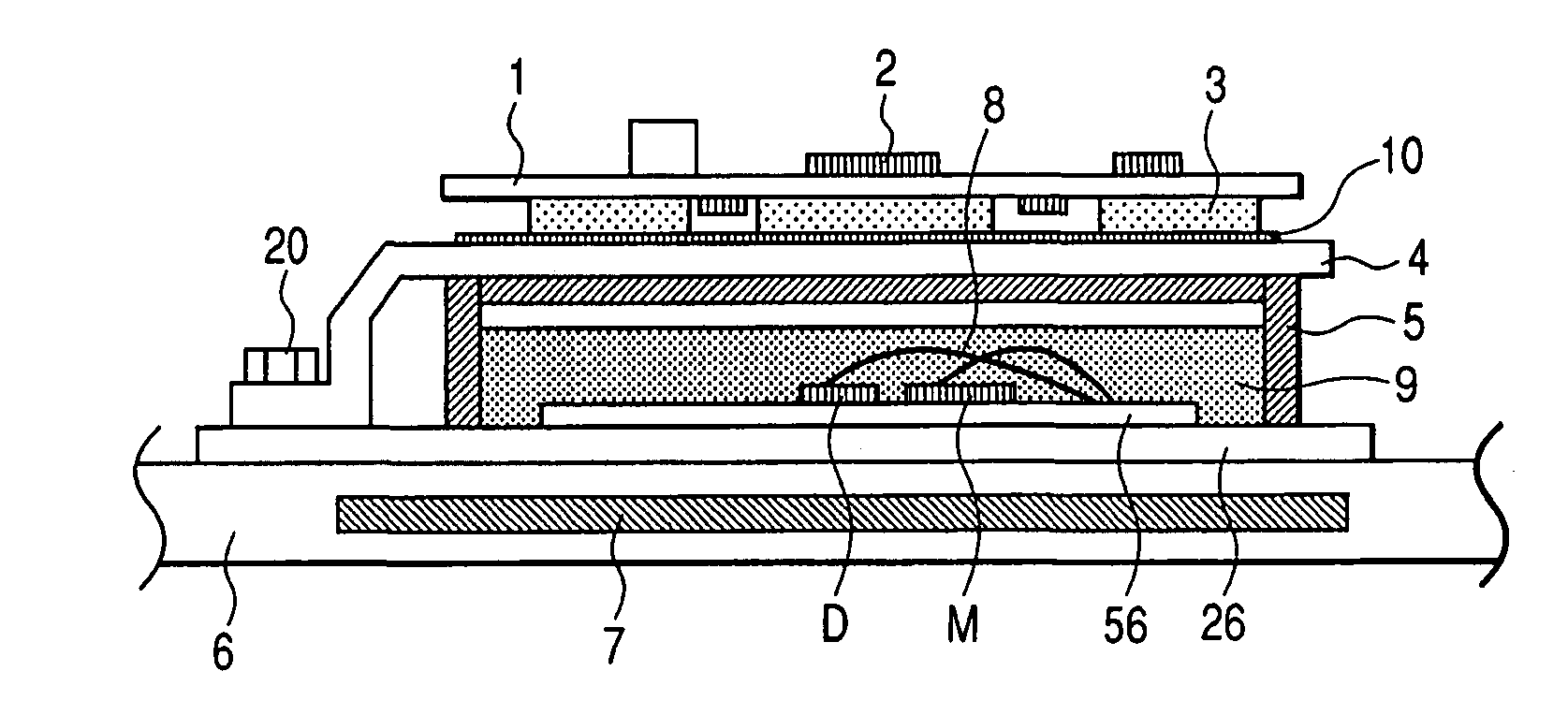
[0085]A cross-sectional view of the structure of the power converter unit 20 which is Example 1 of the present invention is shown in FIG. 7. In FIG. 7, reference numeral 1 indicates a drive circuit board for driving the power semiconductor device, 2 indicates electronic parts on the drive circuit board 1, 3 indicates a heat dissipating sheet, 4 indicates a metal plate, 5 indicates a power module having the power semiconductor device M and the diode D, molded in resin 9, and 6 indicates the metal casing.

[0086]The drive circuit board 1, the heat dissipating sheet 3, the metal plate 4, the power module 5, and the metal casing 6 are assembled in this order from the top.

[0087]A circuit for performing the drive control of the power semiconductor device M of the power module 5 is mounted on the drive circuit board 1 (drive circuit unit DCU). The drive circuit board 1 is fixed to the power module 5, and the control terminals of the drive circuit board 1 and the power module 5 are electrical...

example 2

[0100]Next, the power converter unit, which is Example 2 of the present invention, will be explained. FIG. 8 is a cross-sectional view of a structure of the power converter unit of Example 2, and FIG. 9 shows plan and cross-sectional views of the principal part of the power converter unit.

[0101]The power converter unit of Example 2 has, as in Example 1, the drive circuit board 1, the heat dissipating sheet 3, the metal plate 4, the power module 5, and the metal casing 6 as shown in FIG. 8. However, the structure of Example 2 differs from the structure of Example 1 in that the heat dissipating sheets 3 are disposed only in the thermally affected portions. That is, in the present example, the heat dissipating sheet 3 is divided into two or more sheets, and each heat dissipating sheet 3 is selectively provided directly under heat generating parts such as a driver IC and a photo-coupler. The cost of the heat dissipating sheets 3 can be reduced by selectively providing them directly unde...

example 3

[0112]Now, a power converter unit of Example 3 of the present invention will be described. FIG. 10 is a cross-sectional view showing the structure of the power converter unit of Example 3.

[0113]In Example 3, reference numeral 13 indicates a capacitor module for smoothing a current at the time of switching of the power semiconductor device M, and reference numeral 14 indicates a bus-bar formed as one body with the capacitor module 13. The bus-bar 14 is fastened to the terminal of the power module 5 with screws.

[0114]Generally, when the power semiconductor element M is driven, a steep current flows from the capacitor module 13 to the power semiconductor device. Therefore, if the drive circuit board 1 is located near the bus-bar 14 or the terminal of the power semiconductor device M, it may be affected by the electromagnetic noise of the power semiconductor device and may malfunction. Therefore, in the present example, the metal plate 4 is bent and is provided between the bus-bar 14 be...


PUM


Abstract

A power converter unit comprises: a metal casing; a power module mounted in the metal casing and equipped with two or more power semiconductor devices; a metal plate disposed on the power module and fixed to the metal casing; a heat dissipating sheet disposed on the metal plate; and a drive circuit board disposed on the heat dissipating sheet and is equipped with a control circuit for controlling the power semiconductor devices.

Description

CLAIM OF PRIORITY[0001]The present application claims priority from Japanese Application Serial No. 2006-306115, filed on Nov. 13, 2006, the content of which is hereby incorporated by reference into this application.FIELD OF THE INVENTION[0002]The present invention relates to a power converter unit. In particular, it relates to a power converter unit with an improved heat dissipation property of a drive circuit board for controlling power semiconductor devices.BACKGROUND OF THE INVENTION[0003]Generally, in a power converter unit, in order to reduce the influence of malfunction caused by the noise accompanied on wirings, a drive circuit for driving power semiconductor devices is mounted near the power semiconductor devices. Since the power semiconductor device generate a lot of heat by switching operation, the drive circuit tends to be affected by the heat generated by the power semiconductor devices. Further, in recent years, there is a tendency for the environmental temperature of ...

Claims


Application Information

Patent Timeline
Patent Type & Authority Patents(United States)
IPC IPC(8): H05K7/20
CPCH02M7/003H01L2224/49175H01L2224/45147H01L2224/48091H01L2924/30107H01L2924/13091H01L2924/13055H01L2224/45124H01L2924/1305H01L2924/3025H01L2924/00H01L2924/00014H01L2224/48139H01L2224/49111H01L2924/19107H01L2924/181H01L2924/00011H01L2924/00012
Inventor YAHATA, KOICHIYUKUTAKE, SEIGOAKAISHI, YOSHIO
Owner HITACHI ASTEMO LTD
Why Eureka
Try Eureka