Method and system for thermal control in X-ray imaging tubes

a technology of thermal control and imaging tubes, applied in the field of medical imaging systems, can solve the problems of premature reduction of the critical mechanical properties of the bearing, and high thermal stress on the various components inside the tub

Inactive Publication Date: 2009-07-14
GENERAL ELECTRIC CO
View PDF14 Cites 7 Cited by
  • Summary
  • Abstract
  • Description
  • Claims
  • Application Information

AI Technical Summary

Problems solved by technology

This results in high thermal stresses on the various components inside the tubes.
When X-ray tubes are operated at a high average power, such as five kilowatts (KW) or more, the bearings experience high thermal stresses due to the increased temperature when the bearings are continuously operated at temperatures higher than the safe temperature limit for their operation, the life of the bearings decreases exponentially, thereby resulting in early failure.
This is due in part to premature decreases in the critical mechanical properties of the bearings, such as hardness and yield strength.
Existing thermal barriers in such systems may not provide sufficient heat insulation to the bearings.
This is because thermal management in the imaging tubes is restricted by the operating conditions, which include a very low pressure (e.g., 10−3-10−6 torr) and very high temperatures in the order of 800 degrees Celsius (C) or more near the bearing hub inside the tube.
Most thermal management materials undergo severe physical and chemical degradation in the form of oxidation under such conditions.
Other constraints also are present, such as electrical conductivity to allow high voltage to pass through the anode and cathode.
In addition, known thermal management materials have complex thermal insulator configurations that may require many design changes in existing tubes, thus increasing the cost of manufacture.
Thus, known imaging tube designs do not provide effective thermal management to the bearings and other components in the system at high operating loads.
Further, these systems are not flexible enough to operate for long durations at high operating loads.

Method used


Image

  • Method and system for thermal control in X-ray imaging tubes
  • Method and system for thermal control in X-ray imaging tubes
  • Method and system for thermal control in X-ray imaging tubes

Examples


Embodiment Construction

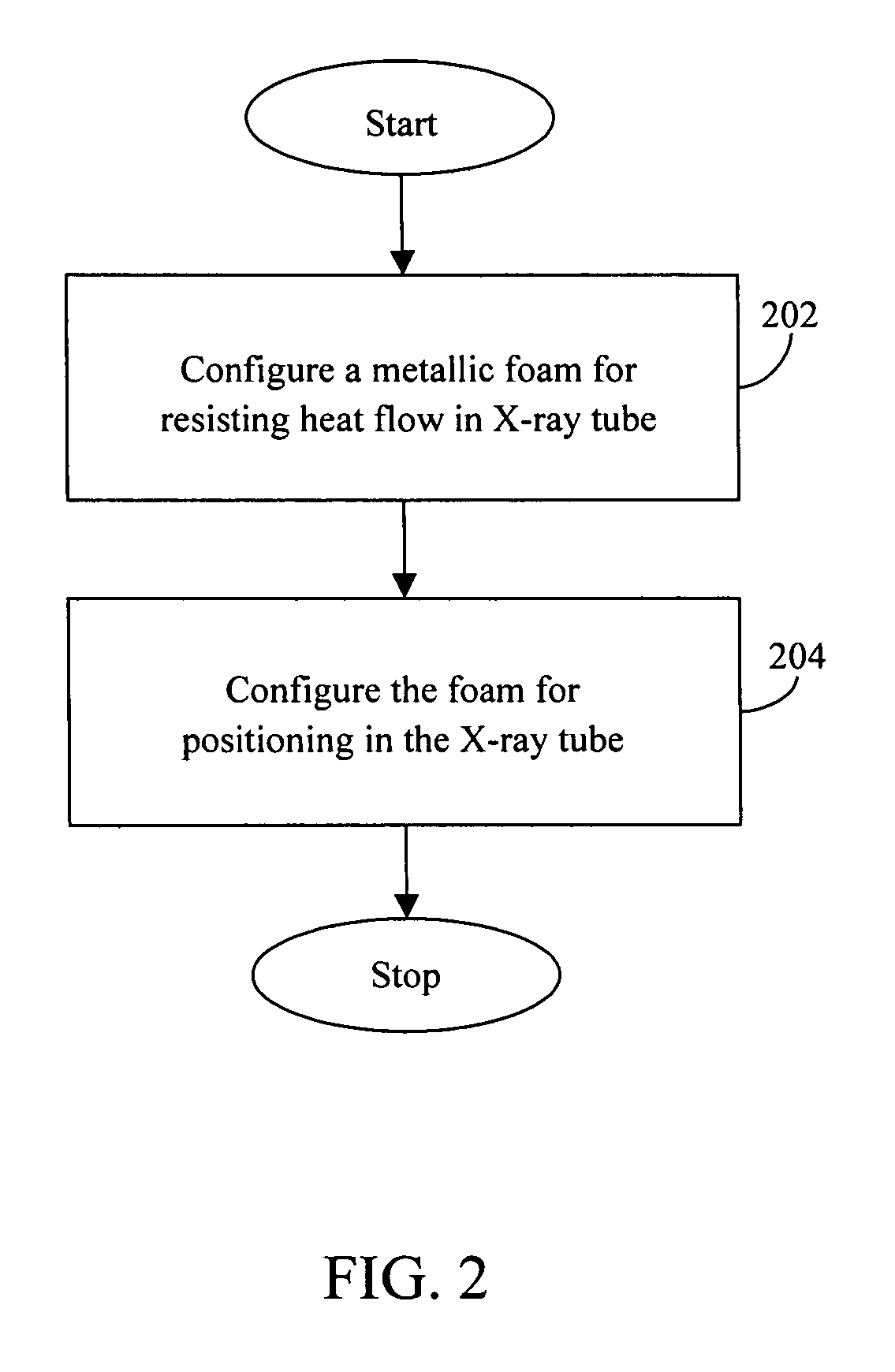
[0019]The various embodiments of the present invention provide methods and systems for thermal protection of components in X-ray tubes. For example, a vacuum compatible metallic foam may be configured and positioned in the X-ray tube to protect the bearings from thermal stresses.

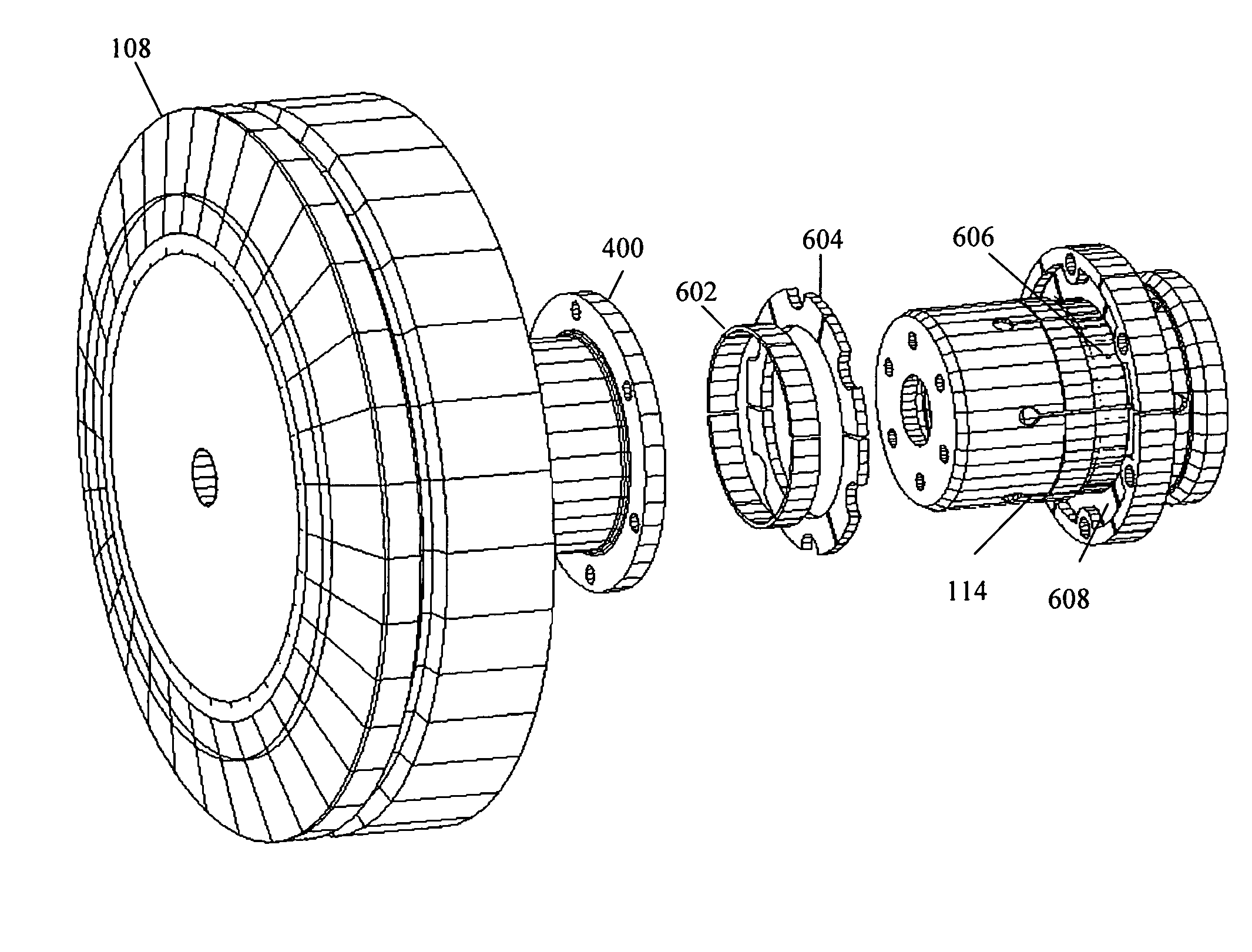
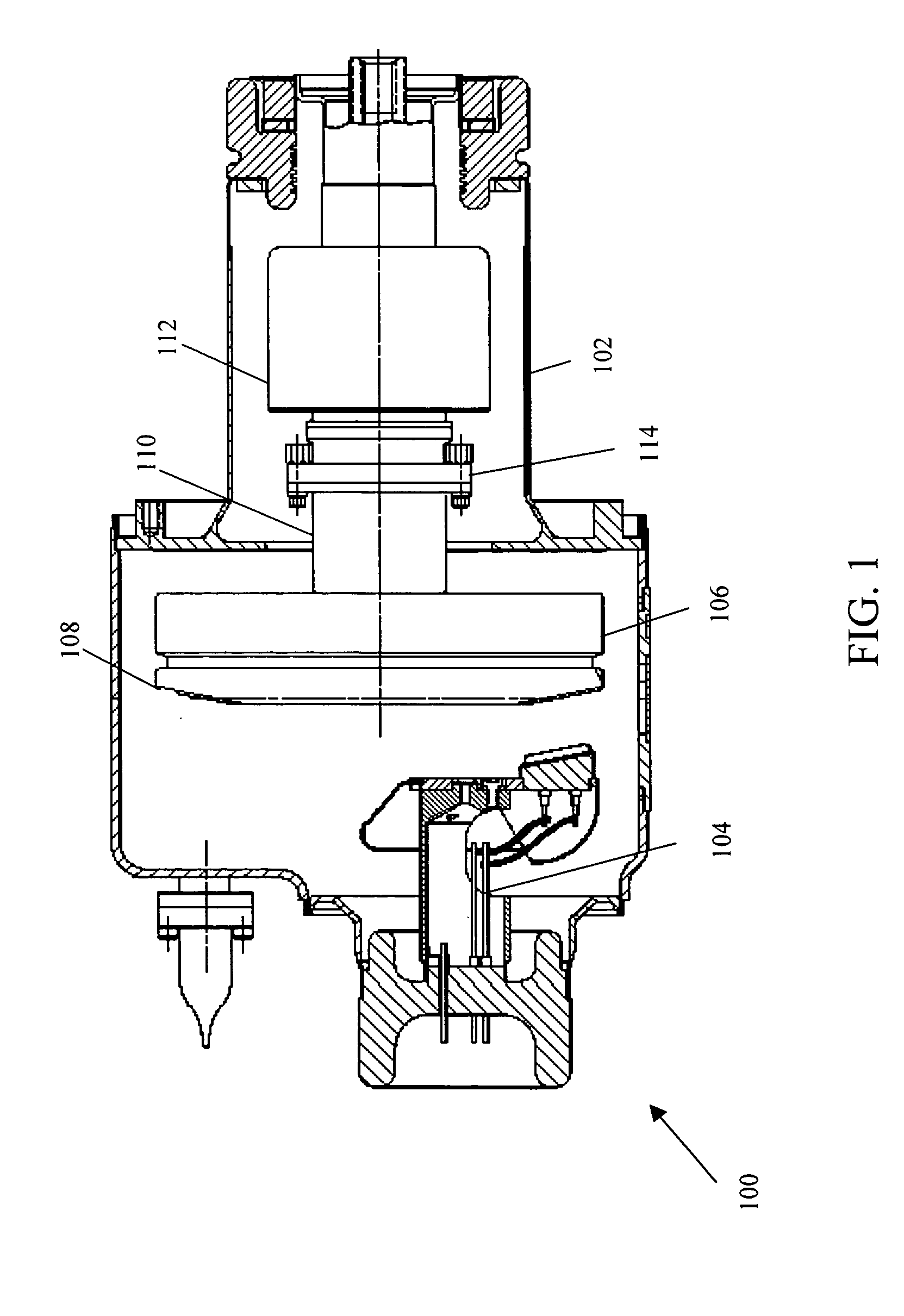
[0020]FIG. 1 is a cross-sectional view of an exemplary X-ray tube in connection with which various embodiments of the present invention may be implemented. An X-ray tube 100 includes a metallic insert 102 within a casing. Insert 102 provides a housing for a cathode assembly 104 and an anode assembly 106. A high vacuum in the order of 10−3-10−6 torr is typically maintained within insert 102. Anode assembly 106 includes a target member 108 connected to a rotor mechanism 112 through a target neck member 110. Target member 108 is subjected to a focused stream of electrons emanating from cathode assembly 104. Rotor 112 spins on internal bearings and enables target member 108 to rotate at high speed during operati...


PUM

PropertyMeasurementUnit
porosityaaaaaaaaaa
porosityaaaaaaaaaa
pressureaaaaaaaaaa

Abstract

Methods and systems for providing thermal insulation in an X-ray tube are provided. The method includes configuring a metallic foam to resist the heat flow in an X-ray tube. The method further comprises configuring the metallic foam for positioning in the X-ray tube to resist heat flow to bearings in the X-ray tube.

Description

BACKGROUND OF THE INVENTION[0001]The present invention relates generally to medical imaging systems. More particularly, the present invention relates to methods and systems for thermal management in X-ray and other imaging tubes.[0002]Imaging tubes such as X-ray tubes, CT tubes and vascular tubes often operate at high average power loads for long durations of time. For example, cardiovascular tubes used for bypass surgery may run continuously for more than forty minutes at high operating loads. This results in high thermal stresses on the various components inside the tubes.[0003]An X-ray tube typically includes a casing and an insert with a cathode assembly and a rotating anode assembly acting as the target. The anode assembly includes a target member, which is rotated at a high speed by attaching the target to a large rotor with the rotor forming the armature of a motor. The rotor typically rotates on a highly specialized ball bearing system.[0004]When X-ray tubes are operated at ...

Claims


Application Information

Patent Timeline
Patent Type & Authority Patents(United States)
IPC IPC(8): H01J35/10H01J35/00H01J35/24H01J35/26H01J35/28
CPCH01J35/10H01J2235/1291H01J2235/1208
Inventor THANGAMANI, ARUNVELRAMAKRISHNA, JAYAPRAKASH
Owner GENERAL ELECTRIC CO
Why Eureka
Try Eureka