
Communication system using ARQ

a communication system and arq technology, applied in the field of communication systems, can solve the problems of wasting a little system resource, adding delay, and inadequacies of fixed bandwidth dedicated links, and achieve the effect of good channel estimates

Active Publication Date: 2009-07-14
KONINKLIJKE PHILIPS ELECTRONICS NV
View PDF16 Cites 44 Cited by
  • Summary
  • Abstract
  • Description
  • Claims
  • Application Information

AI Technical Summary

Benefits of technology

The present invention provides a solution for improving channel estimation in a communication system. It involves a primary station and a secondary station communicating data packets and pilot information. The secondary station increases the transmission power of the pilot information for a predetermined period during which a status signal is transmitted, to improve the accuracy of detecting acknowledgement messages. The primary station controls the power of the uplink control channel and adjusts the power control means for the predetermined period around the expected transmission of the status signal. This solution helps to improve the overall performance of the communication system.

Problems solved by technology

Typically a particular MS will only require such data intermittently, so fixed bandwidth dedicated links are not appropriate.
This only wastes a little system resource.
Without special physical layer mechanisms, this situation can only be recovered from by using higher layer processes, which add delay and represent a significant waste of system resources.

Method used


Image

  • Communication system using ARQ
  • Communication system using ARQ
  • Communication system using ARQ

Examples


Embodiment Construction

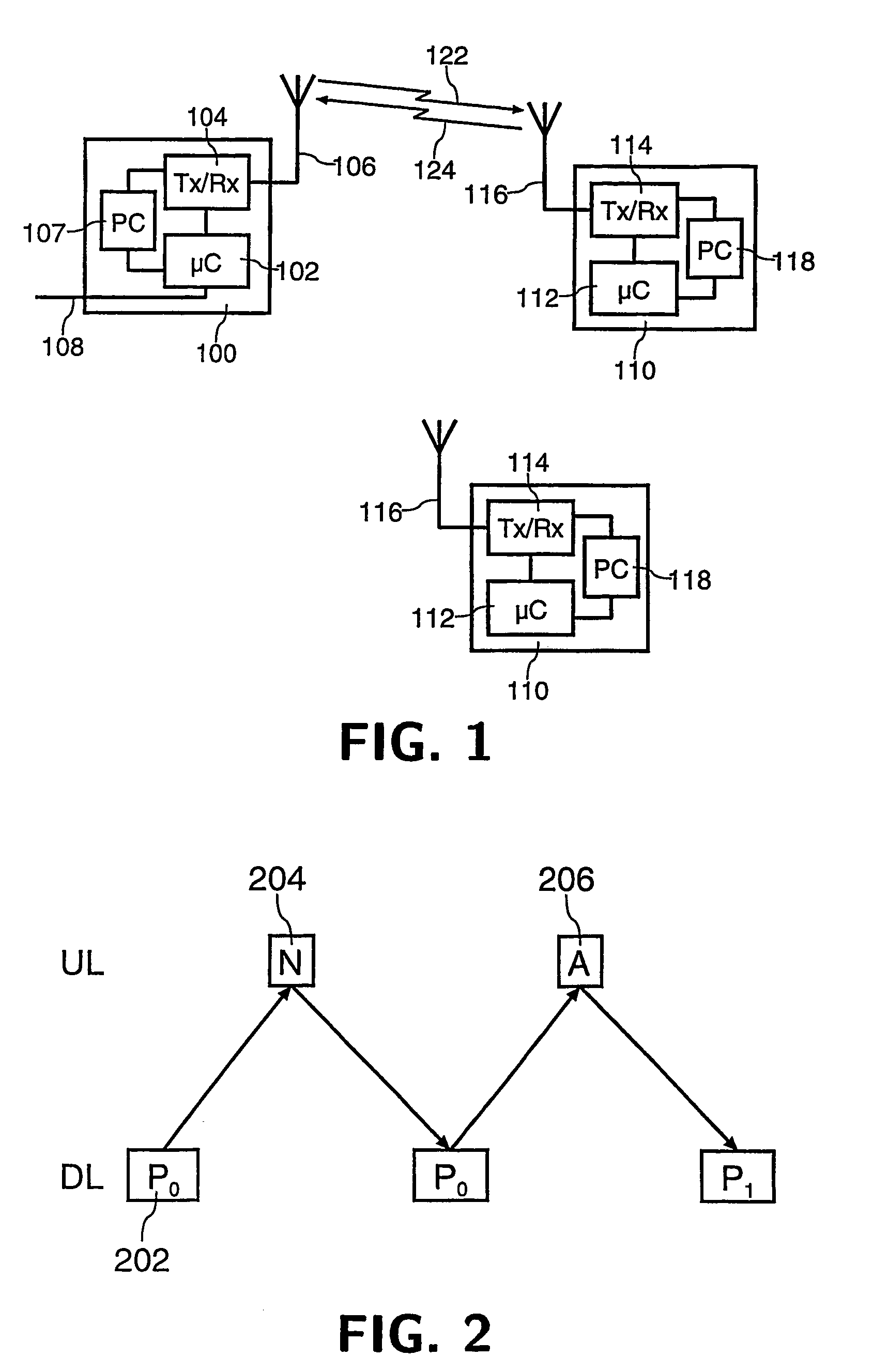
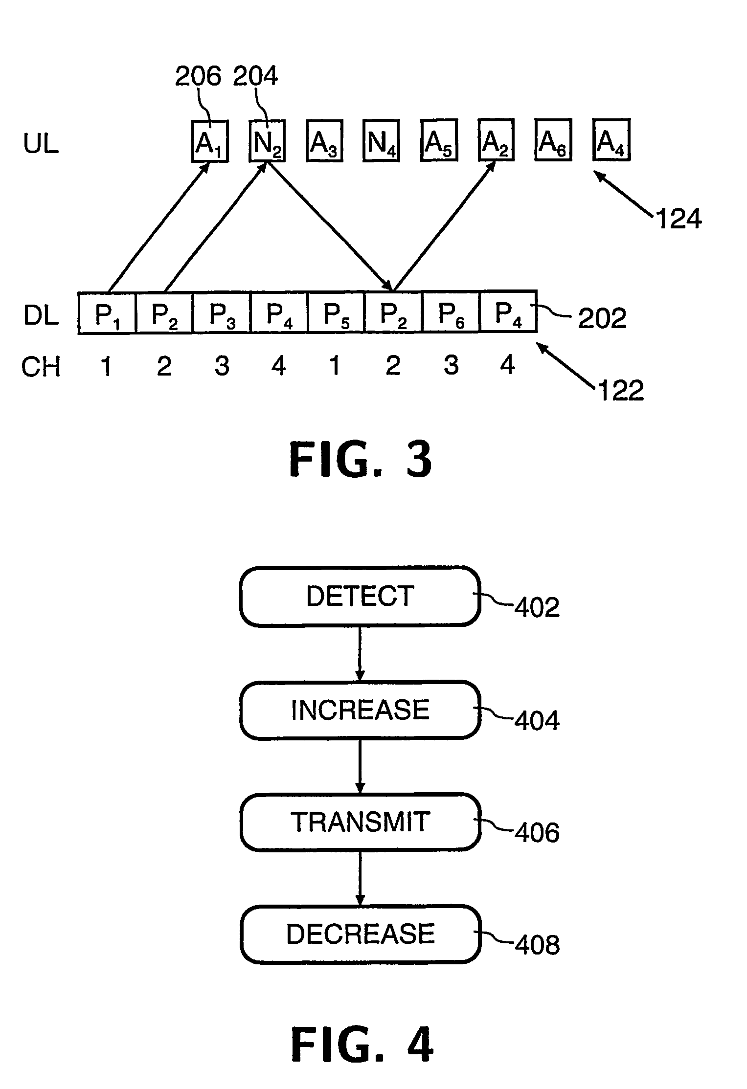
[0018]Referring to FIG. 1, a radio communication system comprises a primary station (BS) 100 and a plurality of secondary stations (MS) 110. The BS 100 comprises a microcontroller (μC) 102, transceiver means (Tx / Rx) 104 connected to antenna means 106, power control means (PC) 107 for altering the transmitted power level, and connection means 108 for connection to the PSTN or other suitable network. Each MS 110 comprises a microcontroller (μC) 112, transceiver means (Tx / Rx) 114 connected to antenna means 116, and power control means (PC) 118 for altering the transmitted power level. Communication from BS 100 to MS 110 takes place on a downlink channel 122, while communication from MS 110 to BS 100 takes place on an uplink channel 124.

[0019]An example of the operation of a known stop-and-wait ARQ scheme is illustrated in FIG. 2. Data packets 202, identified as Pn where n is a one-bit sequence number, are transmitted in allocated time slots on a downlink data channel (DL) 122 from a BS...


PUM


Abstract

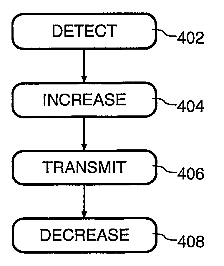
A communication system comprises a downlink data channel for the transmission of data packets from a primary station to a secondary station and two uplink control channels, a first channel for transmission of status signals to indicate the status of received data packets and a second channel for transmission of pilot information. In operation, on detection (402) of a data packet the secondary station increases (404) the transmission power of the second channel, thereby enabling the primary station to obtain a better estimate of uplink channel properties and hence increase the accuracy with which it can decode the status signal. The secondary station transmits (406) the status signal, typically either an acknowledgement (ACK) or negative acknowledgement (NACK), and decreases (408) the transmission power of the second control channel signal. The increase and decrease in power are not necessarily identical, for example as a result of the effects of power control.

Description

TECHNICAL FIELD[0001]The present invention relates to a communication system and further relates to primary and secondary stations for use in such a system and to a method of operating such a system. While the present specification describes a system with particular reference to the Universal Mobile Telecommunication System (UMTS), it is to be understood that such techniques are equally applicable to use in other communication systems.BACKGROUND ART[0002]There is a growing demand in the mobile communication area for a system having the ability to download large blocks of data to a Mobile Station (MS) on demand at a reasonable rate. Such data could for example be web pages from the Internet, possibly including video clips or similar. Typically a particular MS will only require such data intermittently, so fixed bandwidth dedicated links are not appropriate. To meet this requirement in UMTS, a High-Speed Downlink Packet Access (HSDPA) scheme is being developed which may facilitate tra...

Claims


Application Information

Patent Timeline
Patent Type & Authority Patents(United States)
IPC IPC(8): H04B7/00H04B7/005H04B7/26H04L1/12H04L1/16H04L1/18H04L29/08
CPCH04L1/1692H04W52/325H04L1/1809H04L1/1858H04L2001/125Y02B60/50H04W52/36H04W52/48H04W52/50H04W52/286
Inventor MOULSLEY, TIMOTHY J.BAKER
Owner KONINKLIJKE PHILIPS ELECTRONICS NV
Learn More