Cooling device and method of manufacturing the same

a cooling device and cooling technology, applied in indirect heat exchangers, lighting and heating apparatus, heating types, etc., can solve problems such as difficulty in reducing the thickness of the cas

Inactive Publication Date: 2009-07-21
DENSO CORP
View PDF13 Cites 2 Cited by
  • Summary
  • Abstract
  • Description
  • Claims
  • Application Information

AI Technical Summary

Benefits of technology

[0007]The present invention is made in view of the foregoing matter, and it is an object of the present invention to provide a cooling device and a method of manufacturing the same, which is capable of reducing a thickness of the case and reducing pressure loss of a high temperature fluid in a high temperature fluid passage, as compared to the conventional case.
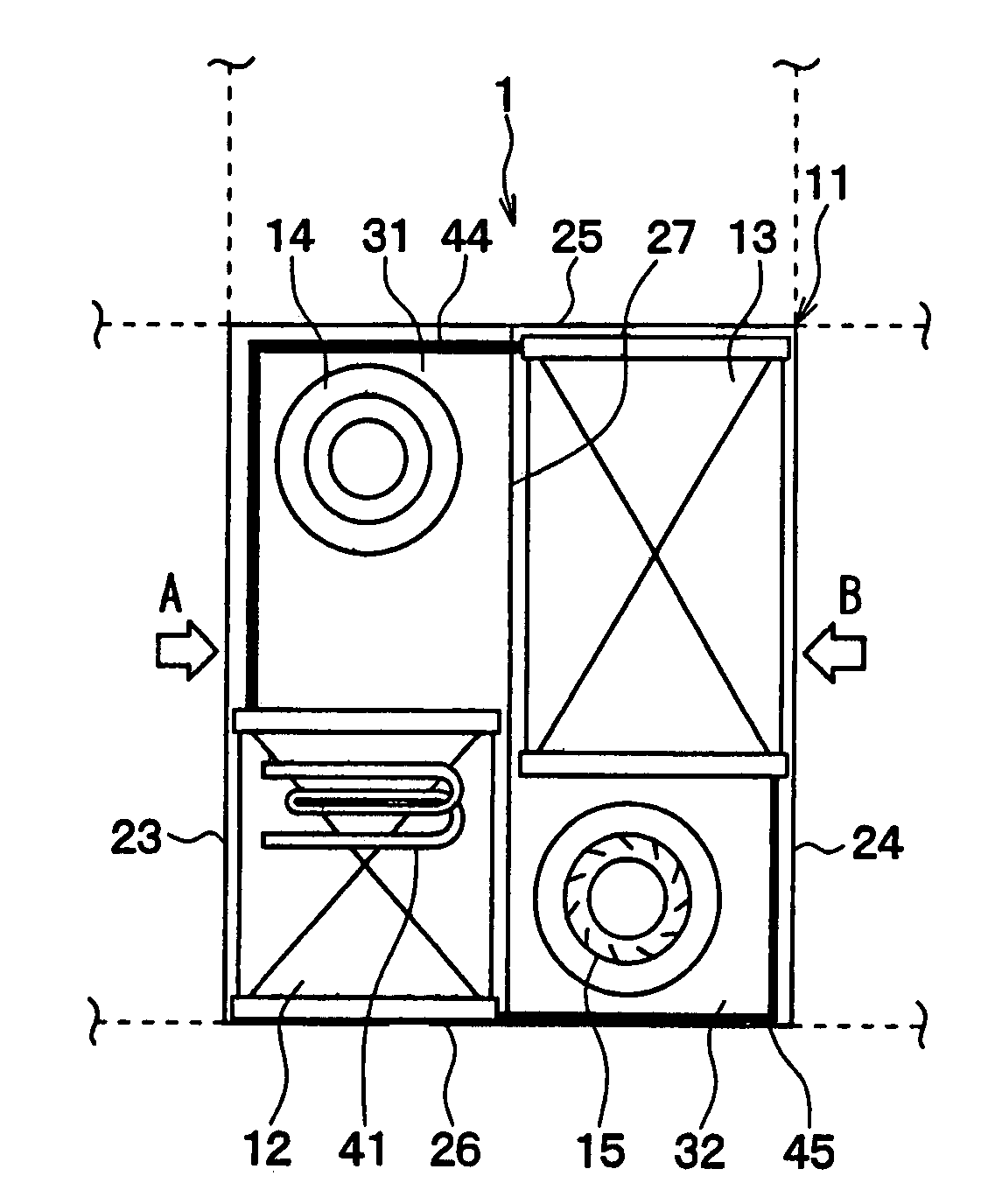
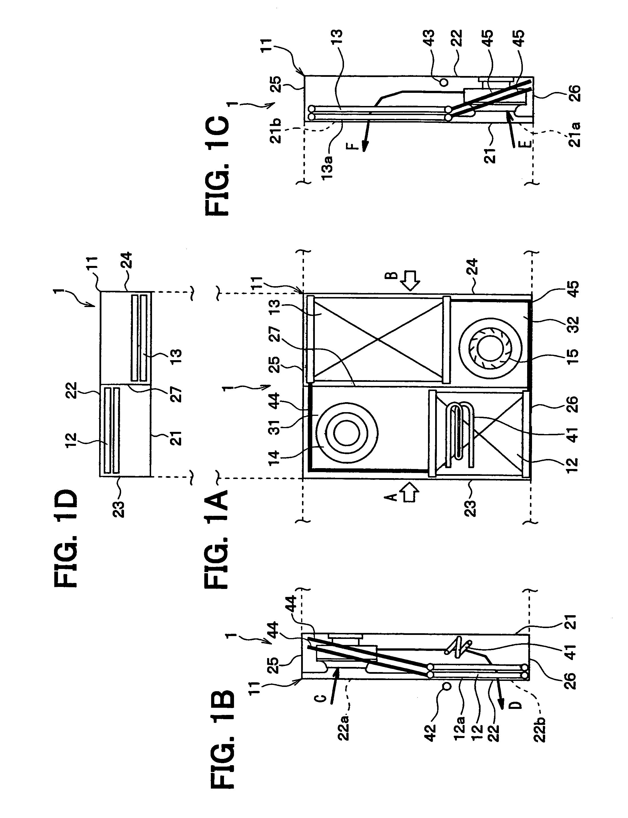
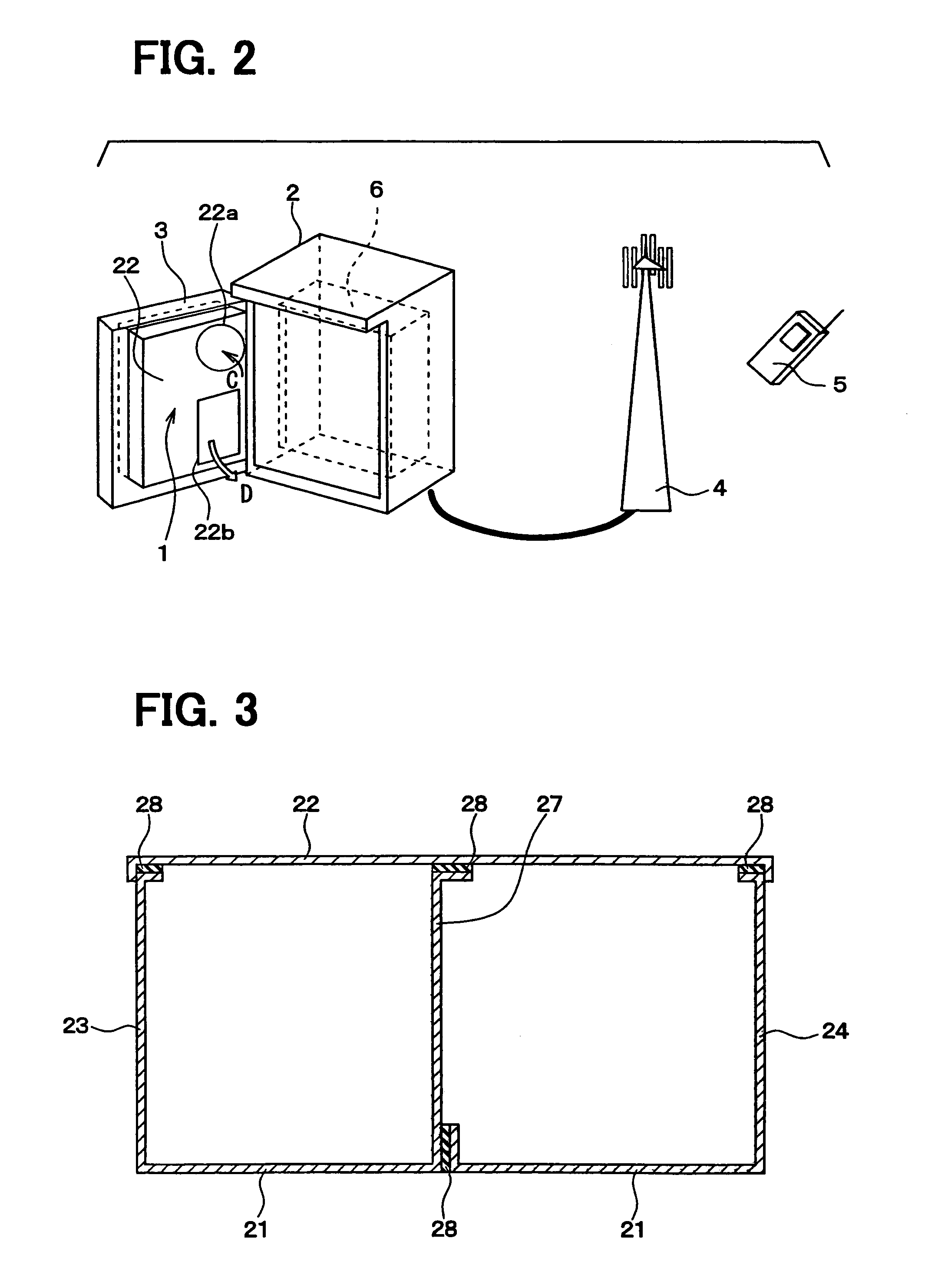
[0010]The first dimension corresponds to a thickness of the case and the second dimension corresponds to a width of the case. Since the first space and the second space are arranged in the second direction, the thickness of the case can be reduced without reducing a passage area of each space, as compared with a conventional case having the same thickness and in which a first space and a second space are arranged in the first direction. The above cooling device has a thinner and slim case, and is for example mounted to a door of a housing accommodating a heating element for cooing air inside of the housing.
[0011]For example, the first space is separated from the second space in the second direction by a partition wall having a generally plate shape. Thus, the case has a simple structure.
[0013]Namely, a gas pipe connecting the first heat exchanger and the second heat exchanger is constructed of at least two pipe sections. A liquid pipe connecting the first heat exchanger and the second heat exchanger is constructed of at least two pipe sections. After the pipe sections are brazed to each of the first and second heat exchangers in the furnace, the separate pipe sections are joined by torch brazing. Accordingly, the connection of the gas pipe and the liquid pipe to the first heat exchanger and the second heat exchanger are performed by furnace brazing, which has reliability higher than that of the torch brazing. Also, the first heat exchanger and the second heat exchanger are brazed separately and then joined to each other by torch brazing. Therefore, it is not necessary to perform brazing in a specific large furnace.

Problems solved by technology

Therefore, it is difficult to reduce the thickness of the case to maintain the high temperature fluid passage on a back side of the low temperature fluid passage in the upper space of the case.

Method used


Image

  • Cooling device and method of manufacturing the same
  • Cooling device and method of manufacturing the same
  • Cooling device and method of manufacturing the same

Examples


second embodiment

[0147]Next, a second embodiment of the present invention will be described with reference to FIG. 11. In the second embodiment, the gas pipe 44 and the liquid pipe 45 are arranged in a different manner from the first embodiment. Structures other than the arrangement of the gas pipe 44 and the liquid pipe 45 are similar to those of the first embodiment. Here, like components are denoted by like reference characters and a description thereof is not repeated.

[0148]As shown in FIG. 11, the upper communication part 52 and the lower communication part 53 of the outside air heat exchanger 13 extend through the partition wall 27 of the case 11. The ends of the upper communication part 52 and the lower communication part 53 are located in the inside of the inside air space 31.

[0149]Similar to the first embodiment, the upper communication part 52 and the lower communication part 53 extend through the holes 27a of the partition wall 27 through the connecting members 61. Thus, clearances betwee...

third embodiment

[0162]A third embodiment of the present invention will be described with reference to FIGS. 12 to 15. Here, like components are denoted by like reference characters and a description thereof is not repeated.

[0163]As shown in FIG. 12, the gas pipe 44 has a pipe joining portion 90 in a midstream of the flow of gas refrigerant. Namely, the gas pipe 44 is constructed of a first gas pipe section 44a connecting to the inside air heat exchanger 12 and a second gas pipe section 44b connecting to the outside air heat exchanger 13. The first gas pipe section 44a and the second gas pipe section 44b are joined to each other at the pipe joining portion 90 by brazing.

[0164]The first gas pipe section 44a and the second gas pipe section 44b have the substantially same length. The pipe joining portion 90 is located at the middle of the length of gas pipe 44. Namely, the pipe joining portion 90 is located at a position furthest from the inside air heat exchanger 12 and the outside air heat exchanger ...

fourth embodiment

[0183]Next, a fourth embodiment of the present invention will be described with reference to FIGS. 16A and 16B. In the fourth embodiment, the inside air heat exchanger 12 has first tubes 51a having a cross-sectional shape shown in FIG. 16A, instead of the tubes 51. Also, the outside air heat exchanger 13 has second tubes 51b having a cross-sectional shape shown in FIG. 16B, instead of the tubes 51.

[0184]In the first embodiment, the passage 55 of the tube 51 of the inside air heat exchanger 12 and the passage 55 of the tube 51 of the outside air heat exchanger 13 have the same equivalent diameter. In the fourth embodiment, however, each passage 55a of the first tube 51a of the inside air heat exchanger 12 has an equivalent diameter larger than that of a passage 55b of the second tube 51b of the outside air heat exchanger 13. Here, the equivalent diameter means a diameter calculated by converting a transverse cross-sectional shape of each passage into a circle.

[0185]The first tube 51a...


PUM


Abstract

A cooling device has a case defining a first space through which a first fluid flows and a second space through which a second fluid having the temperature lower than that of the first fluid flows. A first heat exchanger is disposed in the first space for performing heat exchange between the first fluid and a refrigerant, thereby to evaporate the refrigerant. A second heat exchanger is disposed in the second space for performing heat exchange between the second fluid and the refrigerant evaporated in the first heat exchanger, thereby to transfer heat of the refrigerant to the second fluid. The case defines a first dimension in a first direction and a second dimension in a second direction perpendicular to the first direction in a transverse cross-section. The second dimension is larger than the first dimension. The first space and the second space are arranged in the second direction.

Description

CROSS REFERENCE TO RELATED APPLICATION[0001]This application is based on Japanese Patent Application No. 2005-321337 filed on Nov. 4, 2005 and No. 2006-284964 filed on Oct. 19, 2006, the disclosures of which are incorporated herein by reference.FIELD OF THE INVENTION[0002]The present invention relates to a cooling device for cooling a high temperature fluid by performing heat exchange between the high temperature fluid and a low temperature fluid having a temperature lower than that of the high temperature fluid without mixing the high temperature fluid with the low temperature fluid, and a method of manufacturing the same.BACKGROUND OF THE INVENTION[0003]A cooling device for cooling air in a housing containing a heating element is for example disclosed in Japanese Patent Publication No. 10-190270 (U.S. Pat. No. 6,026,891) and No. 10-2686 (U.S. Pat. No. 6,119,767, U.S. Pat. No. 6,575,230). In the cooling device, a case is generally divided into an upper space and a lower space. A fi...

Claims


Application Information

Patent Timeline
Patent Type & Authority Patents(United States)
IPC IPC(8): F28D1/02F24D19/02
CPCF28D15/0233F28D15/0266F28D15/0275H05K7/20609F28F1/022F28F1/128F28F9/26F28D15/0283
Inventor KADOTA, SHIGERUNISHIZAWA, KAZUTOSHITAKEUCHI, TETSUYAITO, AKIRANAKAMURA, SATORU
Owner DENSO CORP
Why Eureka
Try Eureka