
Laminated piezoelectric element and production method of the same

a piezoelectric element and piezoelectric technology, applied in piezoelectric/electrostrictive/magnetostrictive devices, piezoelectric/electrostriction/magnetostriction machines, generators/motors, etc., can solve the problems of size reduction and sophistication of actuators, and achieve high piezoelectric properties, high piezoelectric properties, and sufficient densification

Active Publication Date: 2009-07-21
TDK CORPARATION
View PDF15 Cites 0 Cited by
  • Summary
  • Abstract
  • Description
  • Claims
  • Application Information

AI Technical Summary

Benefits of technology

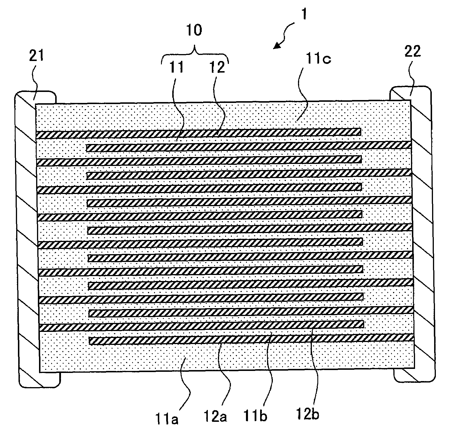
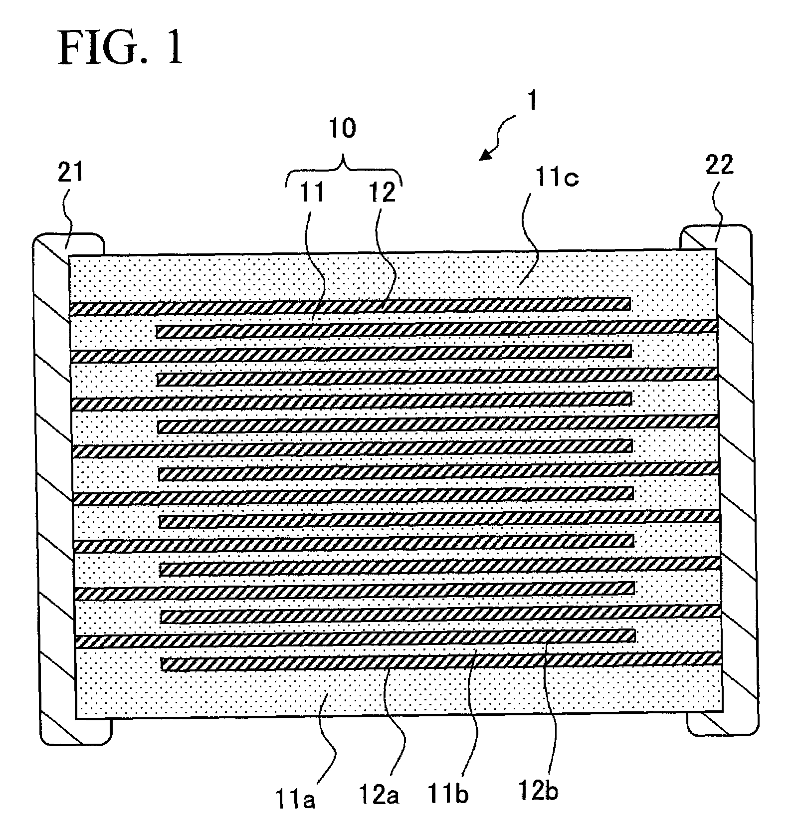
[0012]The present inventors have made various studies on the main constituent and the additives constituting the piezoelectric layers. Consequently, the present inventors have found that Ag2O as an additive is effective as a low-temperature sintering agent, and additionally improves the piezoelectric properties when added in a predetermined amount in relation to a particular main constituent composition. The present invention is based on this finding, and is accordingly a laminated piezoelectric element comprising: a plurality of piezoelectric layers each comprising a composite oxide as a main constituent thereof; and a plurality of internal electrode layers formed between the piezoelectric layers and containing Ag; wherein the piezoelectric layers are each comprised of a sintered body comprising: the composite oxide, as a main constituent thereof, represented by (Pba-bMb)[(Zn1 / 3Nb2 / 3)xTiyZrz]O3 with the proviso that 0.96≦a≦1.03, 0≦b≦0.1, 0.05≦x≦0.15, 0.25≦y≦0.5, 0.35≦z≦0.6, x+y+z=1, and M represents at least one selected from Sr, Ca and Ba; and Ag in a content of 1.0% by weight or less (not inclusive of 0) in terms of Ag2O in relation to the main constituent.
[0015]In the laminated piezoelectric element of the present invention, the Ag-containing internal electrode layers can be constituted of, for example, pure Ag or a Ag—Pd alloy. Because Pd is higher in cost than Ag, and because when the content of Pd is large, Pd undergoes during sintering an oxidation-reduction reaction to lead to a fear that cracks and delamination are thereby caused in the laminated piezoelectric element, thus the content of Pd in the Ag—Pd alloy is preferably 30% by mass or less. When a Ag—Pd alloy having a content of Pd of 30% by mass or less is used for the internal electrode layers, the sintering temperature is required to be set at 1150° C. or lower and preferably 1120° C. or lower on the basis of the Ag—Pd system phase diagram. For the purpose of further reducing the production cost, the content of Pd is required to be lowered, and for that purpose, the sintering temperature of the piezoelectric ceramic composition constituting the piezoelectric layers is required to be made as low as possible. Thus, in the present invention, the adoption of the above-mentioned composition makes it possible to use for the internal electrode layers a Ag—Pd alloy having a content of Pd of 20% by mass or less. As shown in the examples to be described below, the laminated piezoelectric element of the present invention is sufficiently densified even when sinterd at low temperatures of 1000° C. or lower, exhibits high piezoelectric properties, and is large in the displacement magnitude at high voltages.
[0018]According to the present invention, it is possible to provide a laminated piezoelectric element that is sufficiently densified even when sinterd at low temperatures of 1000° C. or lower, exhibits high piezoelectric properties and is high particularly in the piezoelectric properties at high voltages.

Problems solved by technology

In these years, in addition to the demand for the price reduction, demand for size reduction and sophistication of various products leads to demand for size reduction and sophistication for actuators to be used in such products.

Method used


Image

  • Laminated piezoelectric element and production method of the same
  • Laminated piezoelectric element and production method of the same
  • Laminated piezoelectric element and production method of the same

Examples


example 1

[0068]Each of the piezoelectric ceramic composition samples shown in Table 1 was prepared by adding Ag2O in the amount shown in Table 1 in relation to the following main constituent, and was subjected to the evaluation of the piezoelectric properties.

[0069]Main constituent:

(Pb0.995-0.03Sr0.03)[(Zn1 / 3Nb2 / 3)0.1Ti0.43Zr0.47]O3

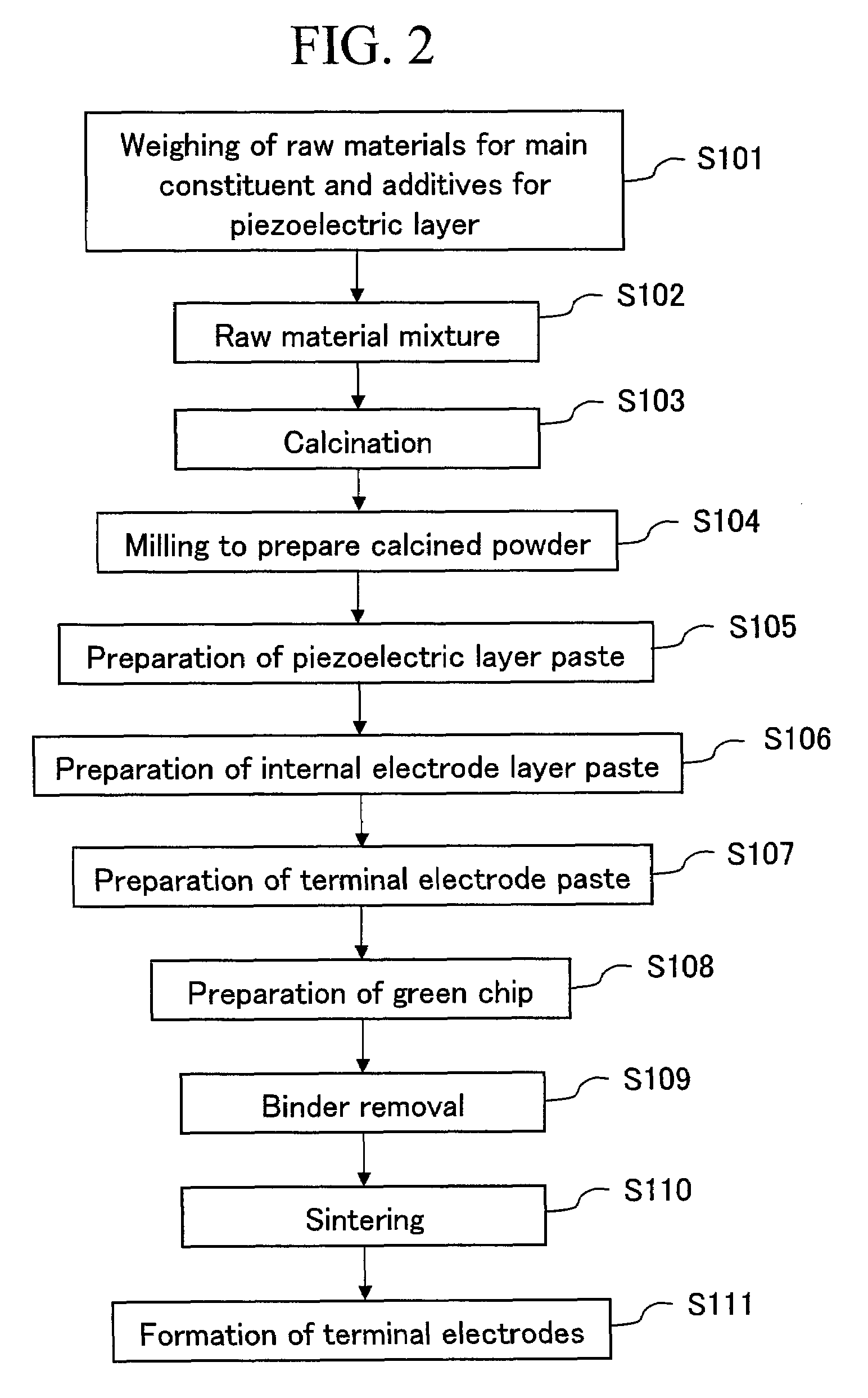
[0070]Each of the piezoelectric ceramic composition samples shown in Table 1 was prepared as follows. First, as the raw materials for the main constituent, a PbO powder, a SrCO3 powder, a ZnO powder, a Nb2O5 powder, a TiO2 powder and a ZrO2 powder were prepared, and were weighed out to give the above-mentioned composition of the main constituent. Additionally, a Ta2O5 powder was added in a content of 0.4% by weight in relation to the main constituent. Then, these raw materials were wet mixed with a ball mill for 16 hours, and calcined in air at 700 to 900° C. for 2 hours.

[0071]The calcined mixture thus obtained was pulverized, added with a Ag2O powder as the addit...

example 2

[0084]Each of the piezoelectric ceramic composition samples shown in Table 2 was prepared by adopting the main constituent composition shown below and by varying a in the composition, in the same manner as in Example 1; the calcined mixture was pulverized, and then Ag2O was added in a content of 0.30% by weight. For each of the piezoelectric ceramic composition samples thus obtained, the displacement magnitude d at the high voltage and the rate of change (d / k31) / (dSTD / k31STD) were obtained in the same manner as in Example 1. The results thus obtained are shown in Table 2. It is to be noted that the (dSTD / k31STD) values for these samples were obtained from the samples in which the main constituent “a” values were 0.96, 0.98, 0.995, 1.005 and 1.03, and Ag2O was not contained.

[0085]Main constituent:

(Pba-0.03Sr0.03)[(Zn1 / 3Nb2 / 3)0.1Ti0.43Zr0.47]O3

[0086]

TABLE 2Main constituentAddition amountRate of changecomposition aof Ag2O (wt %)d (pm / V)(d / k31) / (dSTD / k31STD)0.9600.302771.010.9803161.07...

example 3

[0088]Each of the piezoelectric ceramic composition samples shown in Table 3 was prepared by adopting the main constituent composition shown below and by varying b in the composition, in the same manner as in Example 1; the calcined mixture was pulverized, and then Ag2O was added in a content of 0.30% by weight. For each of the piezoelectric ceramic composition samples thus obtained, the displacement magnitude d at the high voltage and the rate of change (d / k31) / (dSTD / k31STD) were obtained in the same manner as in Example 1. The results thus obtained are shown in Table 3. It is to be noted that the (dSTD / k31STD) values for these samples were obtained from the samples in which the main constituent b values were 0, 0.01, 0.03, 0.06 and 0.1, and Ag2O was not contained.

[0089]Main constituent:

(Pb0.995-bSrb)[(Zn1 / 3Nb2 / 3)0.1Ti0.43Zr0.47]O3

[0090]

TABLE 3Main constituentAddition amountRate of changecomposition bof Ag2O (wt %)d (pm / V)(d / k31) / (dSTD / k31STD)0.000.302901.190.013501.160.033551.130...


PUM

PropertyMeasurementUnit
temperaturesaaaaaaaaaa
thicknessaaaaaaaaaa
thicknessaaaaaaaaaa

Abstract

A laminated piezoelectric element capable of being sintered at low temperatures and high in piezoelectric properties is provided. The laminated piezoelectric element comprises a plurality of piezoelectric layers each comprising a composite oxide as a main constituent thereof and a plurality of internal electrode layers formed between the piezoelectric layers and containing Ag, wherein the piezoelectric layers are each comprised of a sintered body comprising the composite oxide, as a main constituent thereof, represented by (Pba-bMb) [(Zn1 / 3Nb2 / 3)xTiyZrz]O3 with the proviso that 0.96≦a≦1.03, 0≦b≦0.1, 0.05≦x≦0.15, 0.25≦y≦0.5, 0.35≦z≦0.6, x+y+z=1, and M represents at least one selected from Sr, Ca and Ba, and Ag in a content of 1.0% by weight or less (not inclusive of 0) in terms of Ag2O in relation to the main constituent.

Description

BACKGROUND OF THE INVENTION[0001]1. Field of the Invention[0002]The present invention relates to a laminated piezoelectric element such as an actuator, a piezoelectric buzzer, a sound component and a sensor.[0003]2. Description of the Related Art[0004]Typical examples of the piezoelectric element may include an actuator. The actuator taking advantage of the displacement generated by the piezoelectric effect as the mechanical driving source has such advantages that the actuator is small in electric power consumption and in heat release, satisfactory in response, and capable of being reduced in size and weight; thus, the actuator has come to be applied to a wide variety of fields. Piezoelectric ceramic compositions to be used in such an actuator are required to be high in piezoelectric properties, in particular, large in piezoelectric strain constant. As piezoelectric ceramic compositions satisfying such properties, there have been developed, for example, a ternary piezoelectric ceram...

Claims


Application Information

Patent Timeline
Patent Type & Authority Patents(United States)
IPC IPC(8): H01L41/187C04B35/493H01L41/083H01L41/22H01L41/273H01L41/43
CPCC04B35/493H01L41/273H01L41/0477H01L41/1876C04B35/6264C04B2235/3208C04B2235/3213C04B2235/3215C04B2235/3251C04B2235/3258C04B2235/3284C04B2235/3291C04B2235/3294C04B2235/768C04B2235/77C04B2235/79H10N30/877H10N30/8554H10N30/053
Inventor SAKAMOTO, HIDEYAITAKURA, KEISUKESAKAMOTO, NORIMASA
Owner TDK CORPARATION
Learn More