Method and apparatus for synchronized parallel operation of PWM inverters with limited circulating current

Inactive Publication Date: 2009-07-21
ROCKWELL AUTOMATION TECH
View PDF6 Cites 36 Cited by
  • Summary
  • Abstract
  • Description
  • Claims
  • Application Information

AI Technical Summary

Benefits of technology

[0021]In some cases each of the first and second common mode chokes has common mode impedance in the range of 1%-10% of system base impedance. In some cases the first common mode choke is linked to the first, second and third common couplin

Problems solved by technology

The main causes for circulating currents include (1) asynchronous PWM signals (e.g., due to misaligned carrier signals and/or differences in modulating signals); (2) differences in power device characteristics (e.g., differences in switch voltage drops and device switching times; (3) imperfect inverter layouts (e.g., signal delays and mismatched impedances due to unequal cable lengths); and (4) control issues (e.g., inaccurate or unbalanced dead-time compensation, etc.).
Even with synchronized operation, high frequency circulating currents have been known to persist due to signal delays, differences in switching characteristics of power semi-conductors and inverter dead time.
Often, despite synchronizing efforts, large reactors have been required to deal with residual circulating currents.
In general de-rating shou

Method used


Image

  • Method and apparatus for synchronized parallel operation of PWM inverters with limited circulating current
  • Method and apparatus for synchronized parallel operation of PWM inverters with limited circulating current
  • Method and apparatus for synchronized parallel operation of PWM inverters with limited circulating current

Examples


Embodiment Construction

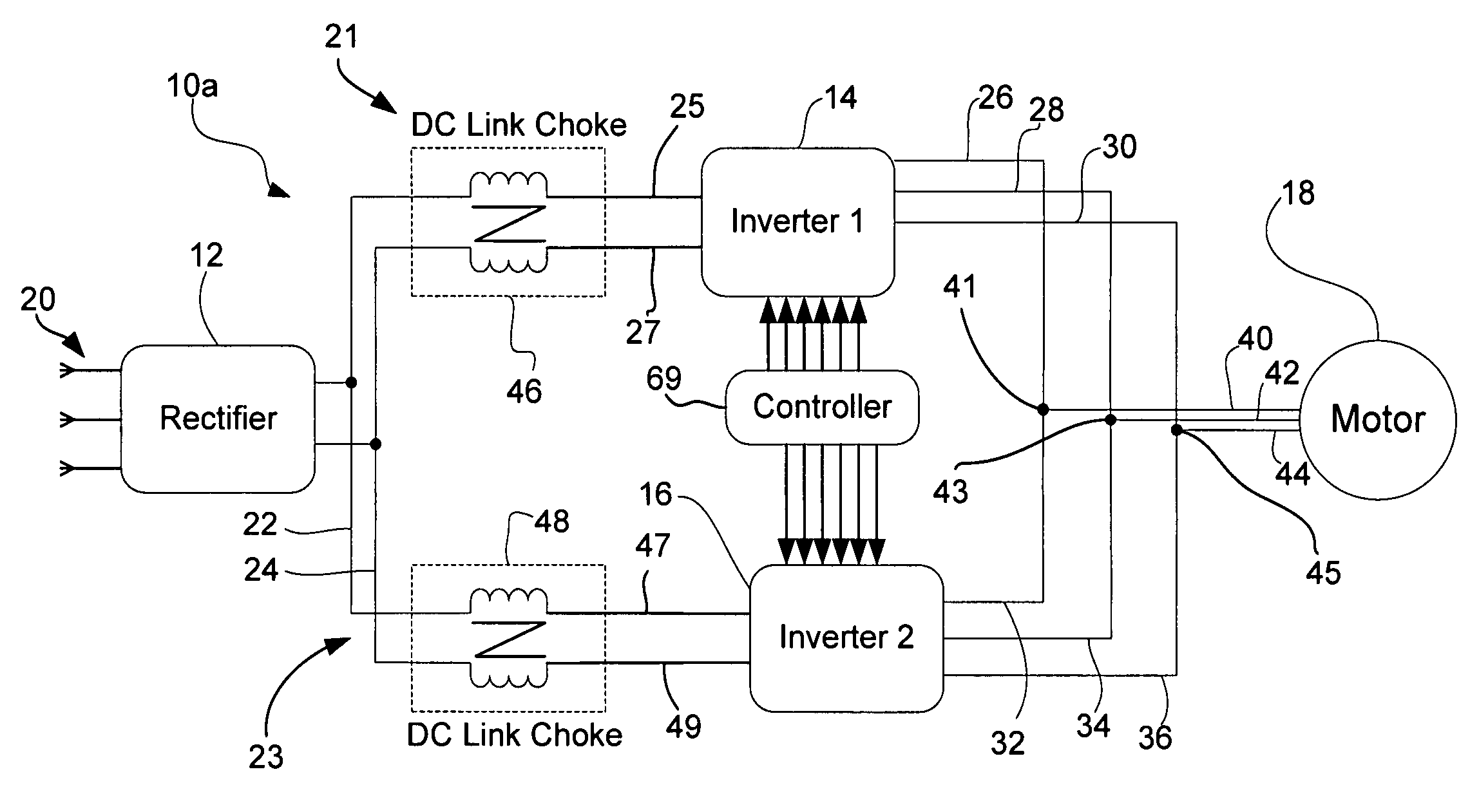
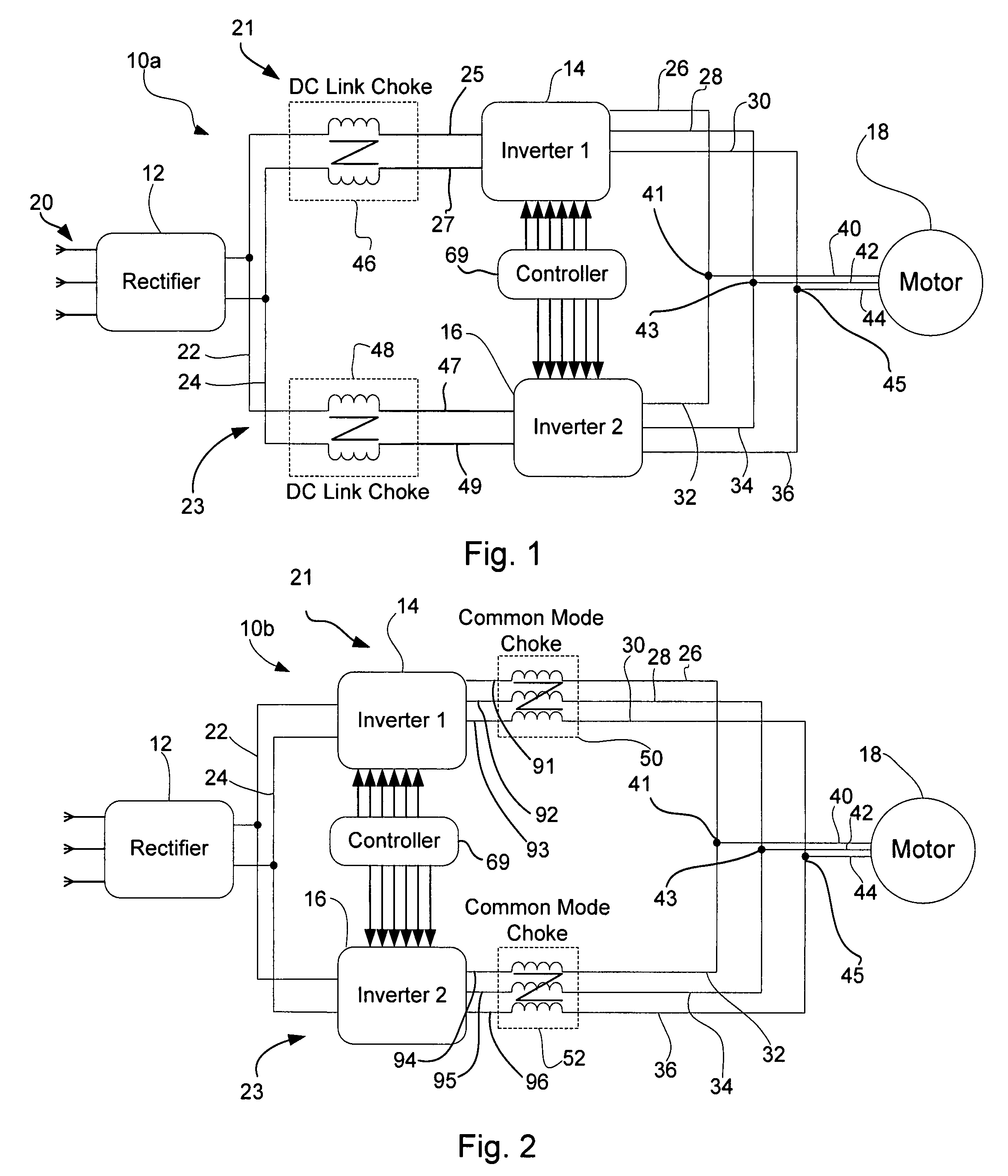
[0032]Referring now to the drawings wherein like reference numerals correspond to similar elements throughout the several views and, more specifically, referring to FIG. 1, the present invention will be described in the context of an exemplary power conversion system 10a that receives power from three AC supply lines collectively identified by numeral 20 and provides three phase AC power to a motor 18 via first, second and third AC output lines 40, 42 and 44, respectively. As shown, system 10a includes a rectifier 12 and first and second parallel system legs 21 and 23. As well known, rectifier 12 receives three phase AC input voltages on supply lines 20 and converts those AC voltages to a DC potential across positive and negative DC rails or buses 22 and 24, respectively.

[0033]Referring still to FIG. 1, first system leg 21 includes a first DC line choke 46, a first three phase inverter 14 and cables 26, 28 and 30. First choke 46 is magnetically linked to positive and negative DC bus...


PUM


Abstract

An apparatus and method for converting DC voltage across positive and negative DC buses to three phase AC voltages on first, second and third AC output lines, the method comprising the steps of providing first and second three phase inverters that include a first subset of inverter switches and a second subset of inverter switches, respectively, linking a first choke in series with the first three phase inverter between the positive and negative DC buses and the AC output lines, linking a second choke in series with the second three phase inverter between the positive and negative DC buses and the AC output lines and synchronously controlling the first and second inverter switch subsets so that switching of first and second inverter switch subsets is substantially synchronized among the three phases.

Description

CROSS-REFERENCE TO RELATED APPLICATIONS[0001]Not applicable.STATEMENT REGARDING FEDERALLY SPONSORED RESEARCH OR DEVELOPMENT[0002]Not applicable.BACKGROUND OF THE INVENTION[0003]The present invention relates to parallel inverter structures with common DC input and more specifically to an apparatus for reducing circulating currents that result when inverters are linked in parallel.[0004]A typical three phase inverter structure includes six switching devices (e.g., IGBTs) that are arranged between positive and negative DC buses of a rectifier apparatus to form first, second and third switch legs where each leg includes a pair of switches. The first leg includes first and second switches arranged in series, the second leg includes third and fourth switches in series and the third leg includes fifth and sixth switches where nodes between each switch pair are linked to different phases of a three phase load. The above topology is generally referred to as a single inverter structure. By co...

Claims


Application Information

Patent Timeline
IPC IPC(8): H02M5/40H02M1/14H02M5/45
CPCH02M7/493H02M1/14H02M1/126H02M2001/123H02M1/123
Inventor BRAUN, DENNISTALLAM, RANGARAJANWIJENAYAKE, AJITHJOHNSON, ROBERT J.
Owner ROCKWELL AUTOMATION TECH
Why Eureka
Try Eureka