Apparatus for loading trays

a technology for trays and accessories, applied in packaging bottles, packaging goods, packaging, etc., can solve problems such as machine jamming, machine process interruption, and easy tipped over vials during handling, and achieve the effect of preventing tipped over and preventing damage to vials

Inactive Publication Date: 2009-07-28
HURST RICHARD F
View PDF10 Cites 3 Cited by
  • Summary
  • Abstract
  • Description
  • Claims
  • Application Information

AI Technical Summary

Benefits of technology

[0005]The invention disclosed herein provides an apparatus for loading process handling trays with medicine vials. The apparatus utilizes an input channel and a discharge channel that are formed with a profile contour configured for holding the vials in upright orientation and preventing tipping. A pusher wheel is similarly formed to capture the vials being conveyed between the pusher wheel and an outer rail. The pusher wheel is further provided with a series of radially extending fingers that move the vials from the input channel to the discharge channel. The fingers are biased to retract and prevent damage to a vial in case of impact by a finger. Adjustment of the spacing between sides of the channels and between the pusher wheel and the outer guide, as well as height adjustment, are provided for vials of different sizes.

Problems solved by technology

However, a unit dose vial is generally a fairly small container, typically on the order of 15 mm in diameter×30 mm high (⅝″×1¼″), making the vial susceptible to being tipped over during handling.
Tipping a glass vial in a machine operation can cause machine jamming, vial breakage, machine process interruption and other problems.
Whereas the apparatus described in the U.S. Pat. No. 6,089,001 is designed to convey vials from a supply conveyor to a handling tray, there is no provision for protecting against vials tipping during transport or for avoiding damage to a vial that may become caught between the index wheel and the circumferential guide.

Method used


Image

  • Apparatus for loading trays
  • Apparatus for loading trays
  • Apparatus for loading trays

Examples


Embodiment Construction

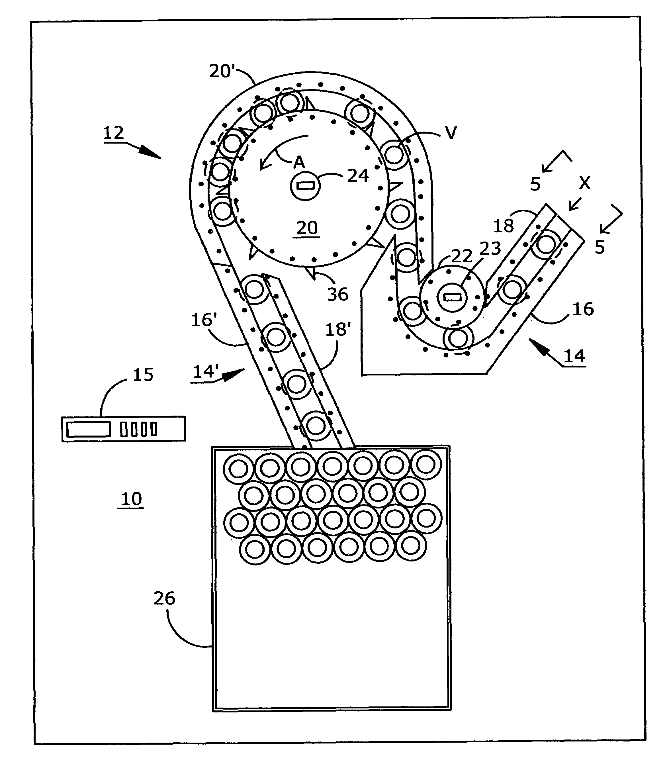
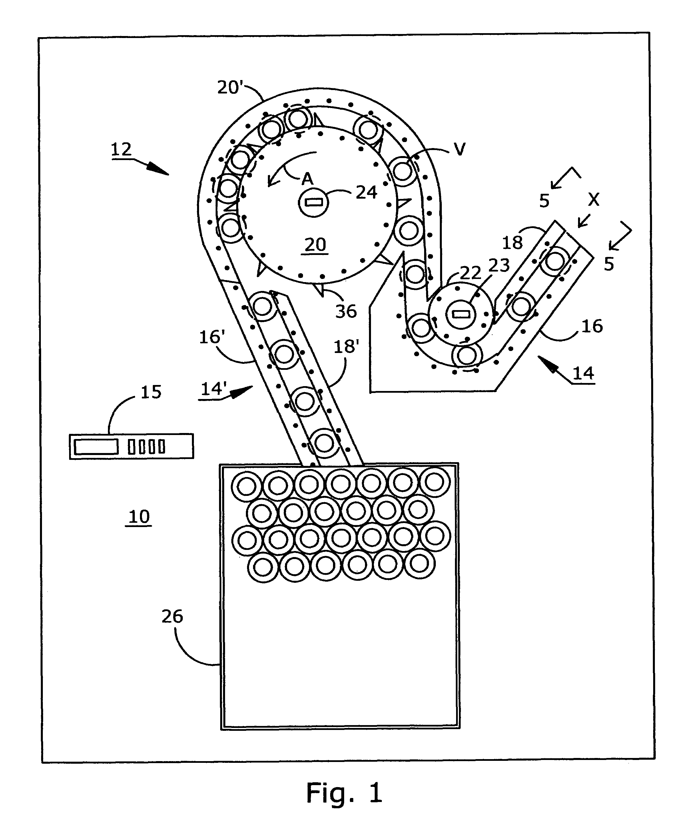
[0012]Referring now to FIG. 1, a substantially level platform 10 is provided to support the tray loading apparatus 12 of the invention. Platform 10 with the apparatus 12 for loading trays may be operated independently or incorporated into a process line in which bottles or vials V are filled, capped, etc. Vials V are loaded on trays 26, e.g. after filling and capping, for ease of handling during autoclaving and other operations. A control panel 15, e.g. a microprocessor, is provided for machine operation and is connected to drives and control circuits such as a counter for replacing a full tray 26 with an empty tray 26 when a selected quantity of vials V has been loaded. Vials V are conveyed from the filling and capping stations preceding the tray loading apparatus 12 of the present invention and introduced at entry X of input channel 14 to travel between an outer guide rail 16 and inner guide rail 18. Outer guide rail 16 and inner guide rail 18 are formed with a contour profile for...


PUM

PropertyMeasurementUnit
diameter×30aaaaaaaaaa
heightaaaaaaaaaa
angleaaaaaaaaaa

Abstract

Apparatus for loading trays with vials receives vials from an input channel and transmits the vials through a discharge channel to a tray for processing, e.g. autoclaving. The vials are conveyed by rotation of a pusher wheel having a series of radially extending, biased fingers on the periphery thereof. An outer guide is located adjacent to the pusher wheel to form a channel for the vials being conveyed. The side edge of the pusher wheel and an opposed side edge of the guide are formed with a lateral protrusion at the upper portion thereof to prevent tipping of the vials.

Description

RELATED APPLICATION[0001]This non-provisional patent application is a conversion of provisional patent application No. 60 / 918,845 filed Mar. 19, 2007.FIELD OF THE INVENTION[0002]The present invention relates to the field of apparatus for automatically loading bottles or vials on trays for handling and further processing, particularly in the pharmaceutical field.BACKGROUND OF THE INVENTION[0003]Medical serums and vaccines are often packaged for shipment in unit dose vials, i.e. vials that contain enough liquid for a single dose. Unit dose vials are typically in the form of a glass container that is sealed after filling with an annular metal closure and a rubber membrane that is captured between the closure and the neck of the vial. This combination of materials is typically not affected by autoclave temperatures and is a cost effective and protective package. However, a unit dose vial is generally a fairly small container, typically on the order of 15 mm in diameter×30 mm high (⅝″×1¼...

Claims


Application Information

Patent Timeline
Patent Type & Authority Patents(United States)
IPC IPC(8): B65B5/10
CPCB65B35/26B65B21/04
Inventor HURST, RICHARD F.
Owner HURST RICHARD F
Why Eureka
Try Eureka