Power source device and charge controlling method to be used in same
a technology of power source device and charge control method, which is applied in the direction of secondary cell servicing/maintenance, instruments, batteries, etc., can solve the problems of unstable power generated by solar cells, degraded reference voltage accuracy, and operating point of solar cells not being at the optimal value, etc., to achieve high efficiency, high accuracy of voltage detection, and effective charging of secondary cells
- Summary
- Abstract
- Description
- Claims
- Application Information
AI Technical Summary
Benefits of technology
Problems solved by technology
Method used
Image
Examples
first embodiment
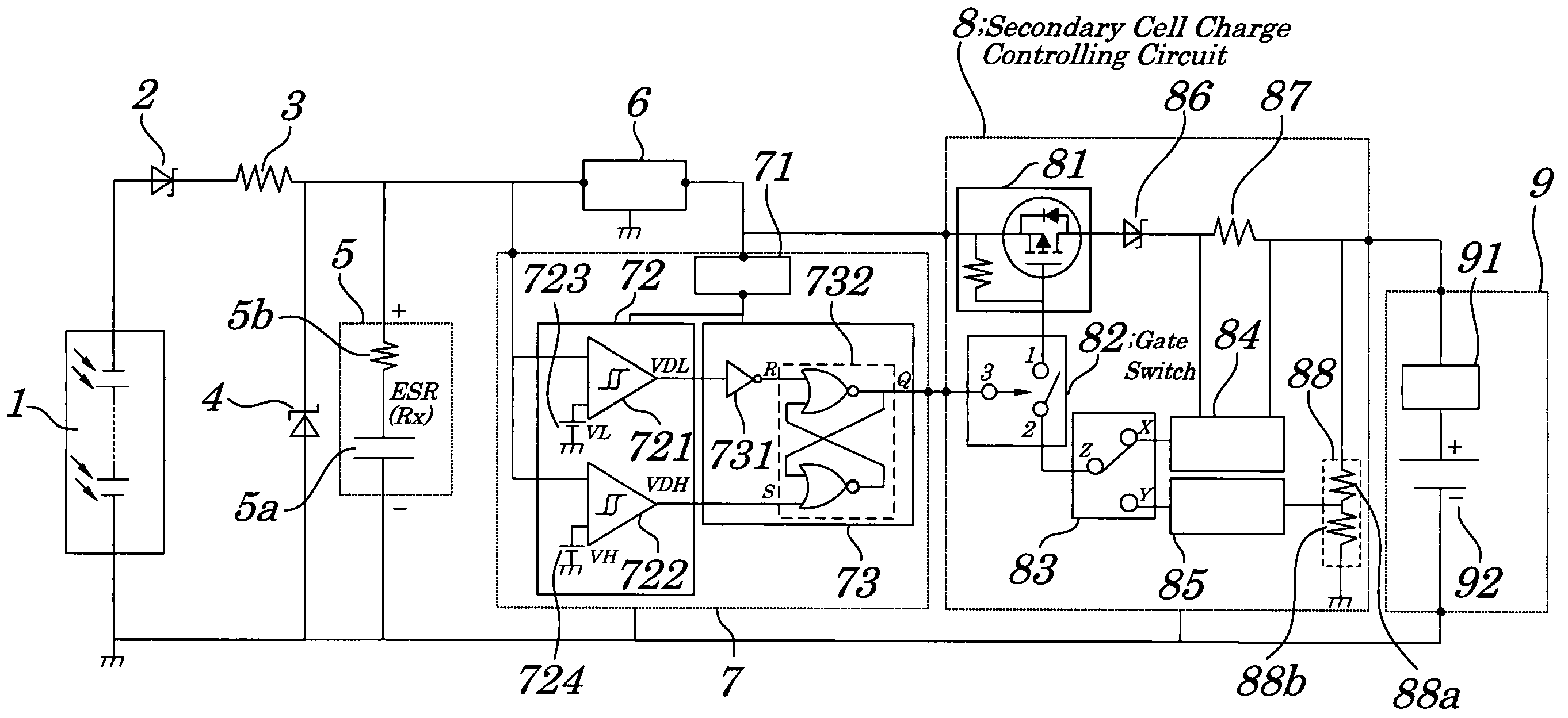
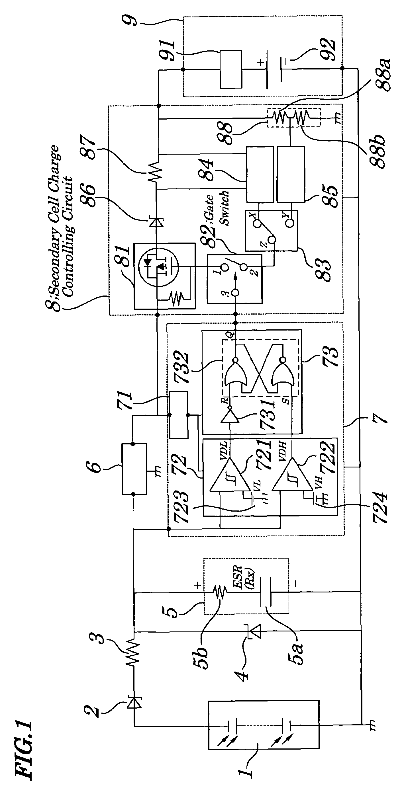
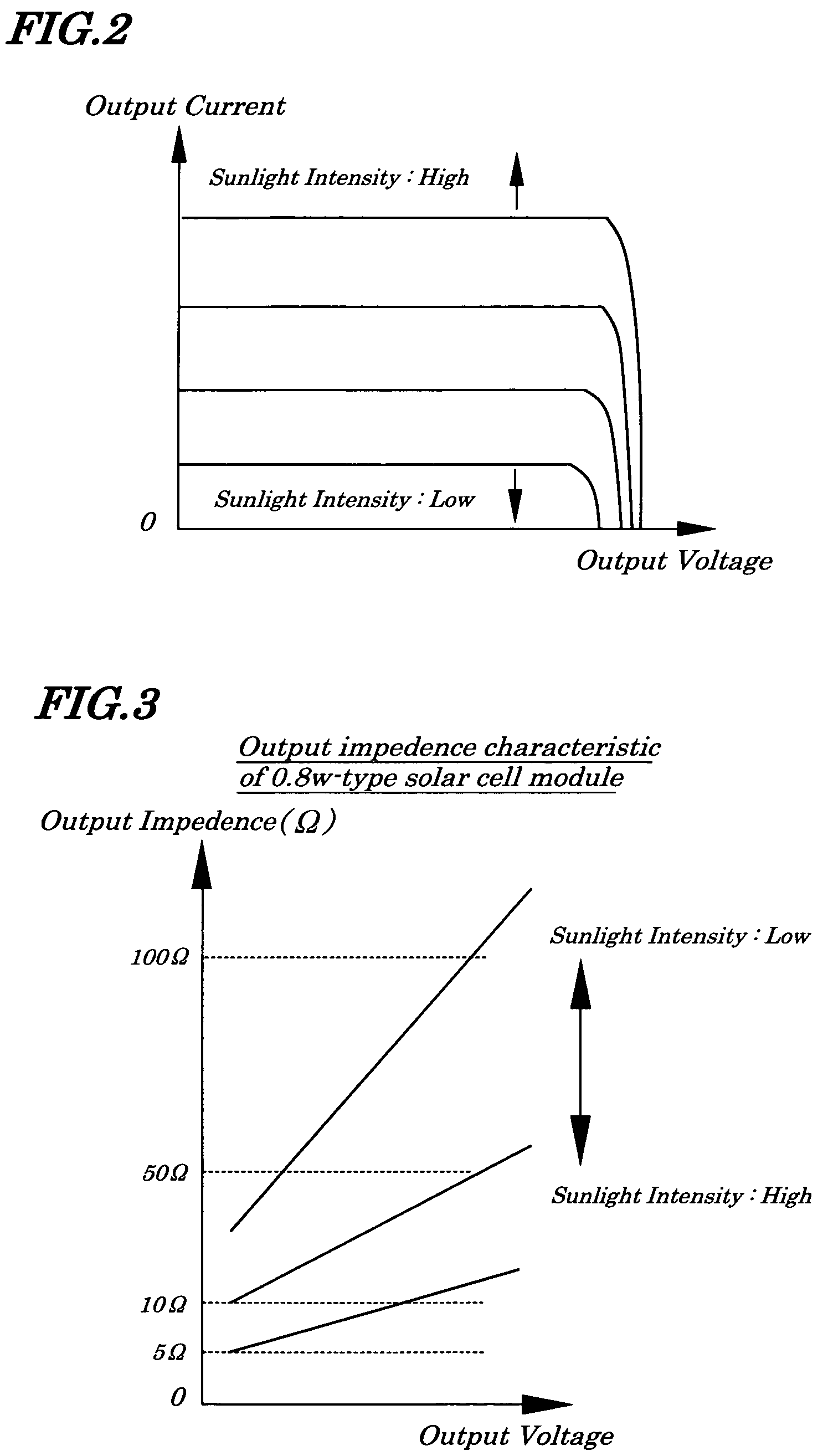
[0057]FIG. 1 is a circuit diagram illustrating electrical configurations of a power source device of a first embodiment of the present invention. The power source device, as shown in FIG. 1, includes a solar cell module 1, a first reverse-current preventing element (device) 2, a current limiting element 3, an overvoltage protecting element (device) 4, an electric double-layer capacitor 5, a booster-type DC (Direct Current)-DC converter 6, a charge on / off controlling circuit 7, a secondary cell charge controlling circuit 8, and a secondary cell pack 9. The solar cell module 1 is made up of a plurality of solar cells being connected (placed) in series and / or in parallel to directly convert sun energy into electrical energy. In the embodiment in particular, the solar cell module 1 is constructed by combining solar cells formed on a substrate made of a silicon semiconductor or a compound semiconductor being arranged in a planar manner and has an output characteristic as shown in FIG. 2,...
second embodiment
[0091]FIG. 11 is a circuit diagram showing electric configurations of a power source device of a second embodiment of the present invention. In FIG. 11, same reference numbers are assigned to components having the same functions as those in FIG. 1. In the power source device of the second embodiment, an output converter 10 is mounted in a back-stage in a secondary cell pack 9 in FIG. 11. The output converter 10 is made up of a DC-DC converter 101 and a DC-DC converter 102. Input terminals of the DC-DC converters 101, 102 are commonly connected to a positive polarity terminal of the secondary cell pack 9. An output A of the DC-DC converter 101 is connected to a load L1; and an output B of the DC-DC converter 102 is connected to a load L2. Other configurations of the components have the same configurations as those in FIG. 1.
[0092]In the power source device of the second embodiment, as in the case of the first embodiment, electric energy converted from sun energy by the solar cell mod...
third embodiment
[0093]FIG. 12 is a circuit diagram showing electrical configurations of the power source device of a third embodiment of the present invention. In FIG. 12, same reference numbers are assigned to components having the same function as those in FIG. 1. The power source device of the third embodiment includes a solar cell module 1, a first reverse-current preventing element 2, a current limiting element 3, a booster-type DC / DC converter 6, a charge on / off controlling circuit 7, a secondary cell charge controlling circuit 8, a secondary cell pack 9, a main capacitor 11, a sub-capacitor 12, a main capacitor overvoltage protecting element 13 (device), a sub-capacitor overvoltage protecting element (device) 14, a main capacitor reverse-current preventing element 15, a sub-capacitor reverse-current preventing element (device) (device) 16, a charging capacitor selecting circuit 17, a capacitor charging voltage comparing circuit 18, and a sub-capacitor discharge controlling circuit 19. The ma...
PUM
| Property | Measurement | Unit |
|---|---|---|
| output impedance | aaaaa | aaaaa |
| withstand voltage | aaaaa | aaaaa |
| impedance | aaaaa | aaaaa |
Abstract
Description
Claims
Application Information
 - R&D
- Intellectual Property
- Life Sciences
- Materials
- Tech Scout
- Unparalleled Data Quality
- Higher Quality Content
- 60% Fewer Hallucinations
Browse by: Latest US Patents, China's latest patents, Technical Efficacy Thesaurus, Application Domain, Technology Topic, Popular Technical Reports.
© 2025 PatSnap. All rights reserved.Legal|Privacy policy|Modern Slavery Act Transparency Statement|Sitemap|About US| Contact US: help@patsnap.com


