Directional coupler

a directional coupler and input port technology, applied in the field of directional couplers, can solve the problems of low return loss of the input port of the directional coupler in a very large frequency range, and achieve the effects of small frequency dependence of the directional coupler according to it, high directivity, and tuning of the directional coupler

Active Publication Date: 2009-07-28
INTEL CORP
View PDF7 Cites 8 Cited by
  • Summary
  • Abstract
  • Description
  • Claims
  • Application Information

AI Technical Summary

Benefits of technology

[0011]An advantage of the invention is that the directional coupler according to it is small-sized. An additional advantage of the invention is that the frequency dependency of the directional coupler according to it is small: High directivity is achieved and the level of the measurement signal in proportion to the level of the signal to be measured is relatively constant in a very large frequency range. Also the return loss of the input port of the directional coupler is low in a very large frequency range. A further advantage of the invention is that the tuning of the directional coupler according to it is simple in production and incurs relatively low costs.
is that the directional coupler according to it is small-sized. An additional advantage of the invention is that the frequency dependency of the directional coupler according to it is small: High directivity is achieved and the level of the measurement signal in proportion to the level of the signal to be measured is relatively constant in a very large frequency range. Also the return loss of the input port of the directional coupler is low in a very large frequency range. A further advantage of the invention is that the tuning of the directional coupler according to it is simple in production and incurs relatively low costs.

Problems solved by technology

Also the return loss of the input port of the directional coupler is low in a very large frequency range.

Method used


Image

  • Directional coupler
  • Directional coupler
  • Directional coupler

Examples


Embodiment Construction

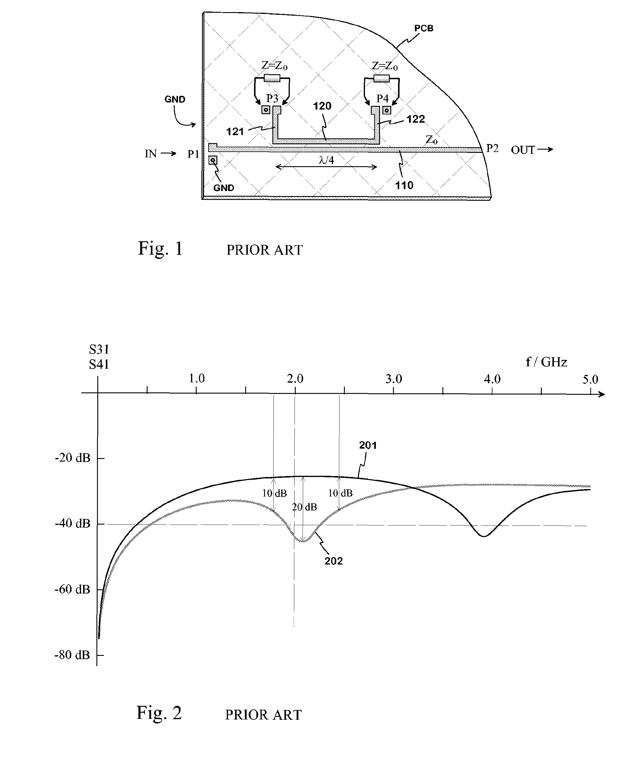
[0020]FIGS. 1 and 2 were already described in connection with the description of prior art.

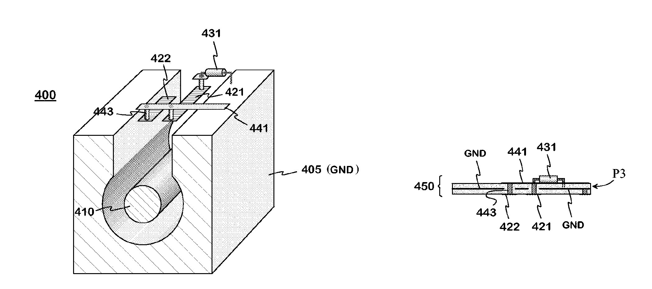
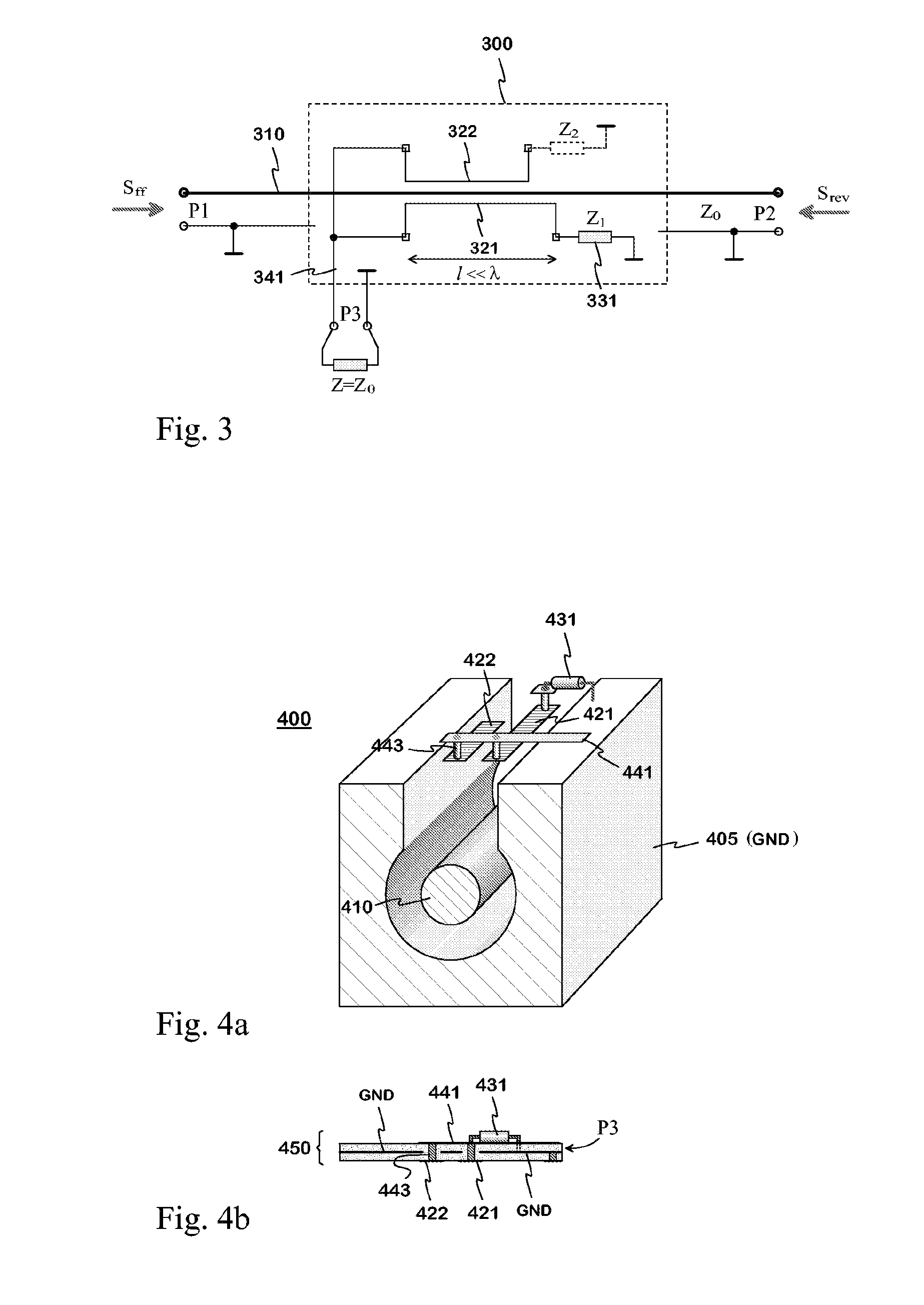
[0021]FIG. 3 is a presentation of the principles of the directional coupler according to the invention. The directional coupler 300 comprises a transmission path including a transmission conductor 310, a ground conductor, or a signal ground GND and their dielectric interspace. In this description and claims, the “interspace” means a space, where the electromagnetic field of a signal propagating on the transmission path significantly exists. The characteristic impedance of the transmission path is Z0. The end of the transmission path through which the forward signal Sff to be measured arrives at the directional coupler is its input port P1, and the other end of the transmission path through which the signal to be measured exits the directional coupler is its output port P2.

[0022]In addition, the directional coupler 300 also comprises, according to the invention, a first 321 and a second 322 sen...


PUM


Abstract

A directional coupler with two sensing conductors and a basic coupler and a supplementary coupler corresponding to them. The basic coupler is based on the coupling between a first sensing conductor (421) and the transmission conductor (410), and the supplementary coupler is based on the coupling between a second sensing conductor (422) and the transmission conductor. The sensing conductors are substantially shorter than a quarter wave, because of which the directivity of both the basic and the supplementary coupler is low. The other ends of the sensing conductors are connected to each other and further to the measurement port of the directional coupler. The coupling signals caused by a reverse signal in the connecting point of the sensing conductors are arranged equal by their absolute value but oppositely phased, in which case their sum signal in the measurement port is insignificantly small. For this purpose, for example, the transmission line formed by the first sensing conductor and the ground is terminated with a matching element at its opposite end, and the transmission line formed by the second sensing conductor and the ground is left open at its opposite end. The termination impedances can be adjustable and the directional coupler thus tunable. In this manner, the directivity of the total directional coupler is improved by means of the second sensing conductor. The directional coupler is small-sized, and good directivity is achieved in a very large frequency range.

Description

[0001]The invention relates to an implementation way of the directional coupler used in radio-frequency circuits.BACKGROUND OF THE INVENTION[0002]The directional coupler is an arrangement related to the transmission path of a radio-frequency electromagnetic field. It gives a measurement signal the level of which is proportional to the strength of a field propagating to a particular direction in the transmission path. In principle, a field propagating to the opposite direction in the transmission path does not affect the level of the measurement signal. The directional coupler has at least three ports: an input, an output and a measurement port. The energy of a signal incoming to the input port is led almost totally through the coupler to the output port, and a small part of this energy is transferred to the measurement port. The part of the directional coupler between the input and output ports is at the same time a part of the transmission path of a radio apparatus which continues,...

Claims


Application Information

Patent Timeline
Patent Type & Authority Patents(United States)
IPC IPC(8): H01P5/18H01P3/06
CPCH01P5/185H01P5/183
Inventor TERVO, MATTI
Owner INTEL CORP
Why Eureka
Try Eureka