Variable reluctance type angle detector

a variable reluctance type and detector technology, applied in the direction of instruments, windings, dynamo-electric components, etc., can solve the problems of insufficient insulation, reduced product yield, increased probability of occurrence of insufficient insulation, etc., and achieve enhanced reliability of the insulation of the variable reluctance type angle detector.

Inactive Publication Date: 2009-08-04
ICHINOMIYA ELECTRIC
View PDF13 Cites 13 Cited by
  • Summary
  • Abstract
  • Description
  • Claims
  • Application Information

AI Technical Summary

Benefits of technology

[0012]This invention was accomplished in view of the above-described background. An object of this invention is to provide a variable reluctance type angle detector with high insulation reliability.
[0015]The excitation wire and the output wire are wound around the tooth members of the stator from outside the end insulator. In each of the tooth members, the partition insulates and separates a part for winding thereon the excitation wire from a part for winding thereon the output wire in the radial direction of the stator. The excitation wire and the output wire are wound around the parts insulated and separated by the partition. With such constitution, the excitation wire and the output wire are reliably insulated from each other. Therefore, reliability of insulation of the variable reluctance type angle detector is enhanced.

Problems solved by technology

In general, along with an increase in contact portion between wires, a probability for occurrence of insufficient insulation is increased.
The incipient failure due to the insufficient insulation reduces a yield of product.
The insufficient insulation with time deteriorates reliability of the product.

Method used


Image

  • Variable reluctance type angle detector
  • Variable reluctance type angle detector
  • Variable reluctance type angle detector

Examples


Embodiment Construction

[0024]Hereinafter, this invention will be described in detail with reference to the drawings and based on preferred embodiments.

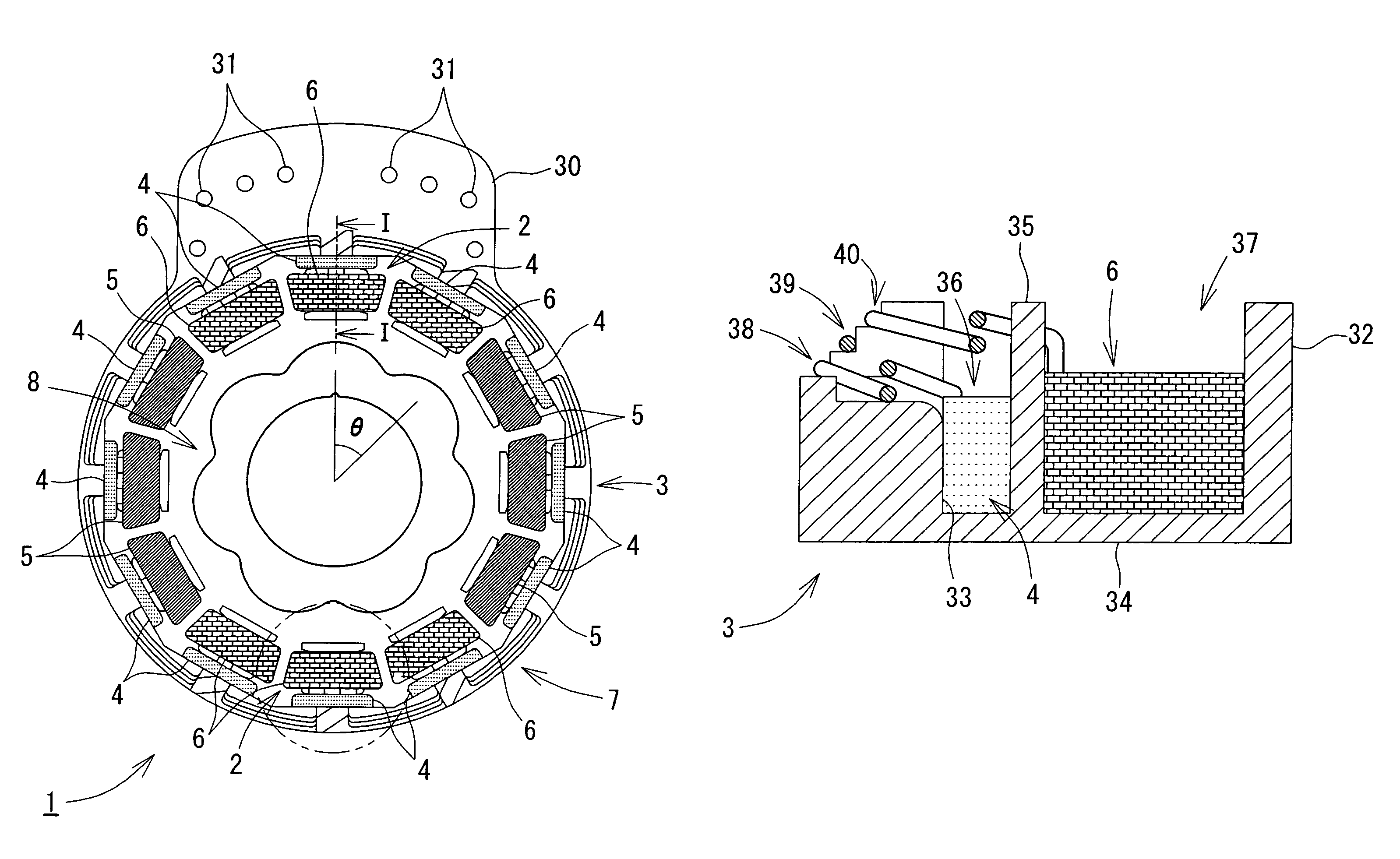
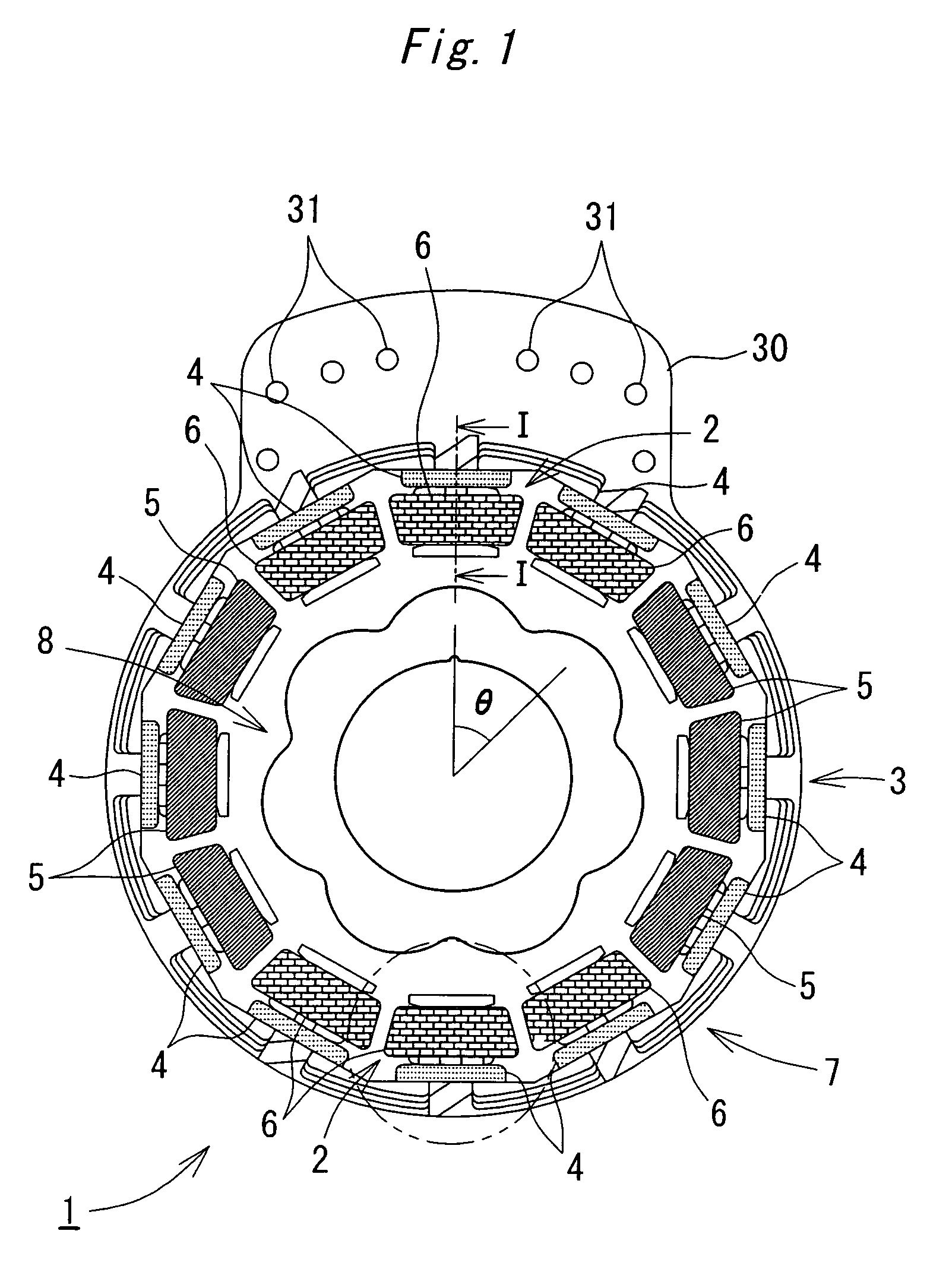
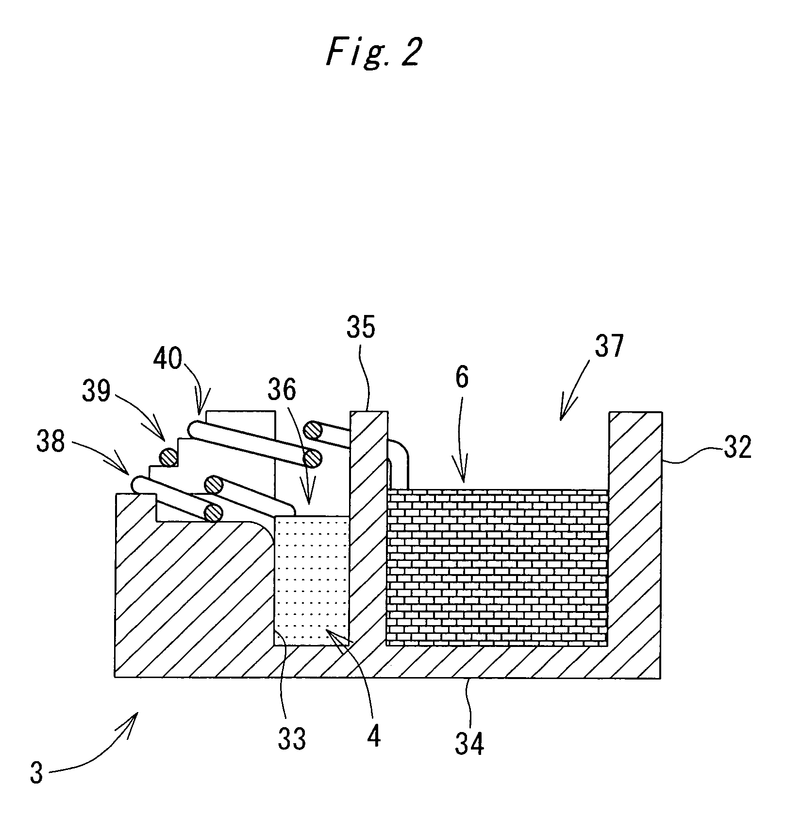
[0025]Shown in FIG. 1 is a main structure of a variable reluctance type angle detector 1 according to one embodiment of this invention. As shown in FIG. 1, the variable reluctance type angle detector 1 is provided with a stator 7 and a rotor 8 disposed rotatably at the center of the stator 7. The stator 7 has twelve tooth members 2 disposed in a circle and projected inward. Insulating coating by an end insulator 3 is provided on the tooth members 2. An excitation wire 4 and output wires 5 and 6 are wound from the outside of the end insulator 3.

[0026]As shown in FIG. 1, an overall outer shape of the stator 7 is substantially in the form of a ring. The twelve tooth members 2 project radially inward from an inner periphery of the stator 7. The stator 7 has a stator core and the end insulator 3. The stator core is formed by pressing a steel plate having a prede...


PUM


Abstract

The variable reluctance type angle detector has a stator and a rotor. The rotor is provided rotatably with respect to the stator. The stator has a plurality of tooth members disposed in a circle. An excitation wire and an output wire are wound around the tooth members. The rotor has such a shape that a gap permeance with respect to the stator varies in a sine wave fashion with respect to an angle θ. The stator is provided with an end insulator for insulating and covering the tooth members. The end insulator is provided with partitions each insulating and separating the excitation wire from the output wire wound around each of the tooth members in a radial direction of the stator.

Description

CROSS REFERENCE TO RELATED APPLICATION[0001]This application claims priority from Japanese Patent Application No. 2005-299773 filed Oct. 14, 2005. The entire content of this priority application is incorporated herein by reference.BACKGROUND OF THE INVENTION[0002]1. Field of the Invention[0003]This invention relates to a variable reluctance type angle detector comprising a rotor having such a shape that a gap permeance varies in a sine wave fashion with respect to an angle θ, the rotor being rotatable with respect to a stator in which an excitation wire and an output wire are wound around tooth members.[0004]2. Description of the Related Art[0005]As a conventional variable reluctance type angle detector, the one having a rotor provided rotatably inside a stator is known. The stator has a stator core provided with twelve tooth members, for example, projecting inward and disposed in a circle. An excitation wire and a two-phase output wire are wound around each of the tooth members of ...

Claims


Application Information

Patent Timeline
Patent Type & Authority Patents(United States)
IPC IPC(8): H02K19/20G01B7/30H02K3/46
CPCH02K24/00G01D5/2053G01D5/2046
Inventor IJIMA, YASUO
Owner ICHINOMIYA ELECTRIC
Why Eureka
Try Eureka