Conversion mixer with high impedance circuit

a high-impedance circuit and conversion mixer technology, applied in the field of conversion mixers, can solve problems such as serious power consumption, and achieve the effects of avoiding the dead zone phenomenon, reducing the influence of the loading circuit on the couple of output signals, and extending the operation rang

Active Publication Date: 2009-08-04
VIA TECH INC
View PDF2 Cites 8 Cited by
  • Summary
  • Abstract
  • Description
  • Claims
  • Application Information

AI Technical Summary

Benefits of technology

[0013]In view of the foregoing, the invention is to provide a conversion mixer capable of reducing the power consumption and having linear output signals of larger operational range.
[0016]As mentioned above, the conversion mixer of the invention utilizes the mixing circuit to mix the couple of first high-frequency input signals with the couple of second high-frequency input signals and then output the couple of low-frequency mixed signals. Also, the duplicating circuit duplicates the couple of mixed signals into the couple of duplicated signals, and then the loading circuit outputs the couple of output signals. Compared with the prior art, the duplicating circuit can separate the mixing circuit from the loading circuit so that the influence of the loading circuit on the couple of output signals is reduced, and the couple of output signals is changed with the influence of the couple of first input signals. Alternatively, using the high impedance circuit can shunt the DC and AC components of the couple of mixed signals so that the DC component of the large signal in the couple of mixed signals passes through the high impedance circuit, and only the AC component of the small signal in the couple of mixed signals is sent to the duplicating circuit. According to this manner, the couple of output signals is only influenced by the couple of first input signals, and the output signal is small, such that the couple of output signals is linear and has the above mentioned larger operation range while avoiding the dead zone phenomenon. In addition, the current value of the duplicated signal can be reduced by adjusting the ratio of the channel regions of the transistors in the current mirror of the duplicating circuit so that power consumption can be reduced.

Problems solved by technology

Also, because the Gilbert-cell mixer 1 needs to utilize the higher supply current I, its power consumption becomes a serious problem.

Method used


Image

  • Conversion mixer with high impedance circuit
  • Conversion mixer with high impedance circuit
  • Conversion mixer with high impedance circuit

Examples


first embodiment

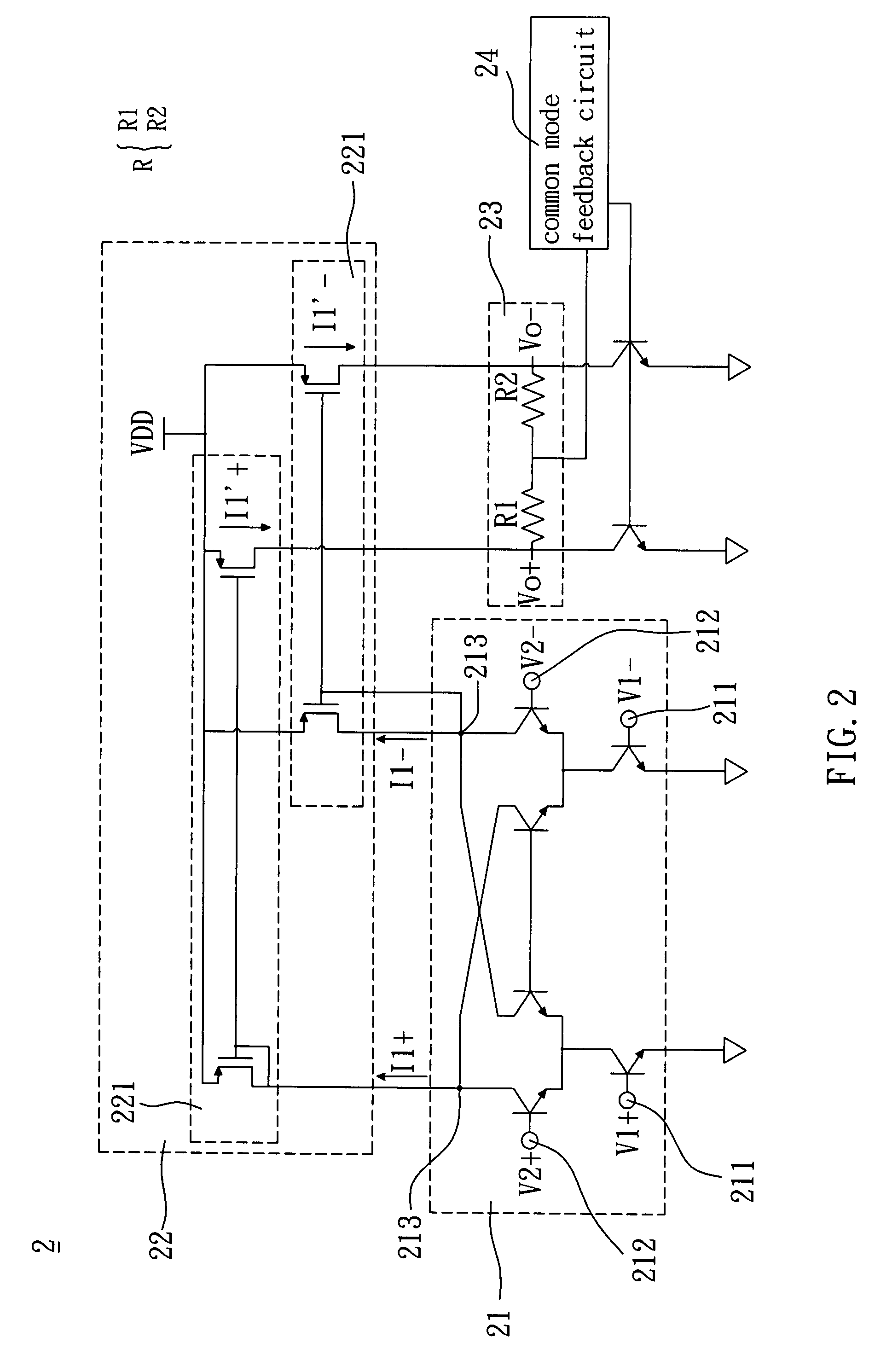
[0023]Referring to FIG. 2, a conversion mixer 2 according to the invention includes a mixing circuit 21, a duplicating circuit 22 and a loading circuit 23. The conversion mixer 2 of this embodiment may be a direct down-sampling conversion mixer.

[0024]The mixing circuit 21 of this embodiment includes a first differential input terminal 211, a second differential input terminal 212 and a differential output terminal 213. The first differential input terminal 211 and the second differential input terminal 212 respectively receive a couple of first input signals V1+ and V1− and a couple of second input signals V2+ and V2−. The mixing circuit 21 mixes the couple of first input signals V1+ and V1− with the couple of second input signals V2+ and V2− and thus outputs a couple of mixed signals I1+ and I1− from the differential output terminal 213. The couple of first input signals V1+ and V1− and the couple of second input signals V2+ and V2− are high-frequency signals, and the couple of mix...

second embodiment

[0030]In addition, referring to FIG. 3, a conversion mixer 3 according to the invention includes a mixing circuit 21, a duplicating circuit 22 and a loading circuit 23. The mixing circuit 21 receives a couple of first input signals V1+ and V1− and a couple of second input signals V2+ and V2−, and mixes the couple of first input signals V1+ and V1− with the couple of second input signals V2+ and V2− to output a couple of mixed signals I2+ and I2−. The duplicating circuit 22 coupled to the mixing circuit 21 receives the couple of mixed signals I2+ and I2−, and duplicates the couple of mixed signals I2+ and I2− to output a couple of duplicated signals I2′+ and I2′−. The loading circuit 23 coupled to the duplicating circuit 22 receives the couple of duplicated signals I2′+ and I2′−, and outputs a couple of output signals Vo+ and Vo− according to the couple of duplicated signals I2′+ and I2′−.

[0031]The conversion mixer 3 of this embodiment further includes a common mode feedback circuit ...

third embodiment

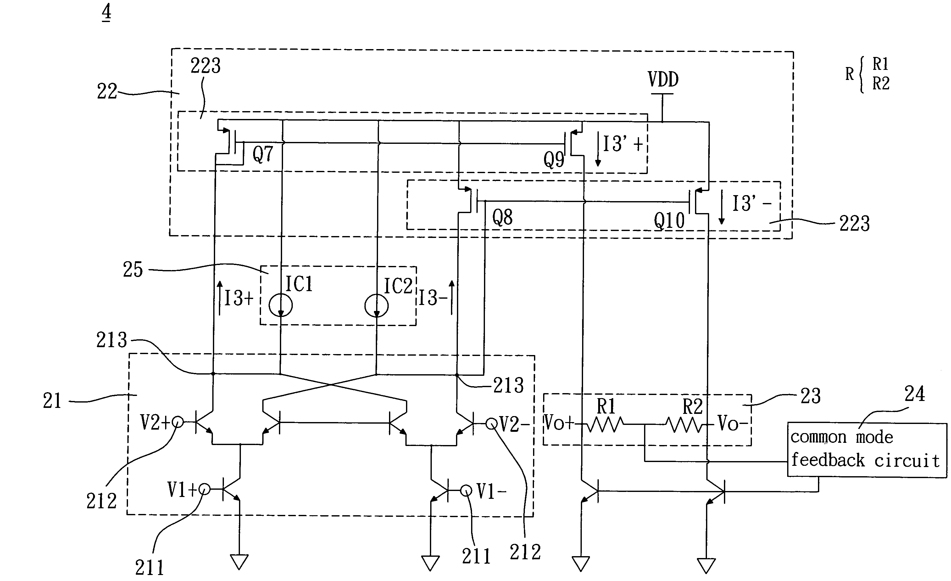
[0035]Referring to FIG. 4, a conversion mixer 4 according to the invention includes a mixing circuit 21, a duplicating circuit 22, a high impedance circuit 25, a loading circuit 23 and a common mode feedback circuit 24.

[0036]The mixing circuit 21 receives a couple of first input signals V1+ and V1− and a couple of second input signals V2+ and V2−, and mixes the couple of first input signals V1+ and V1− with the couple of second input signals V2+ and V2− to output a couple of mixed signals I3+ and I3−, which are small signal currents in practice. The high impedance circuit 25 coupled to the mixing circuit 21 and the duplicating circuit 22 guides the couple of mixed signals I3+ and I3− to be input to the duplicating circuit 22. In addition, the duplicating circuit 22 has to be coupled to the mixing circuit 21, receives the couple of mixed signals I3+ and I3− and duplicates the couple of mixed signals I3+ and I3− to output a couple of duplicated signals I3′+ and I3′−.

[0037]In this embo...


PUM


Abstract

A conversion mixer includes a mixing circuit, a duplicating circuit and a loading circuit. The mixing circuit receives a couple of first input signals and a couple of second input signals and mixes the couple of first input signals with the couple of second input signals to output a couple of mixed signals. The duplicating circuit coupled to the mixing circuit receives the couple of mixed signals and duplicates the couple of mixed signals to output a couple of duplicated signals. The loading circuit coupled to the duplicating circuit receives the couple of duplicated signals and outputs a couple of output signals according to the couple of duplicated signals.

Description

[0001]This Nonprovisional application claims priority under 35 U.S.C. §119(e) on U.S. Provisional Application Nos. 60 / 799,325 filed on May 11, 2006, the entire contents of which are hereby incorporated by reference.BACKGROUND OF THE INVENTION[0002]1. Field of Invention[0003]The invention relates to a conversion mixer, and, in particular, to a conversion mixer for converting a high-frequency input signal into a low-frequency output signal.[0004]2. Related Art[0005]In microwave communication technology, because radio frequency (RF) signals in a transceiver cannot be easily processed, the received radio frequency signal is modulated and down-sampled to a baseband signal to facilitate the subsequent signal processing procedures.[0006]Currently, a conversion mixer for mixing and modulating the radio frequency signal with a local oscillation signal and thus generating a new middle signal is often added to an RF front-end circuit of the transceiver. In addition, the conversion mixer also c...

Claims


Application Information

Patent Timeline
Patent Type & Authority Patents(United States)
IPC IPC(8): G06G7/44
CPCH03D7/145H03D7/1491H03D2200/0084H03D2200/0033
Inventor LIN, CHEN-CHINGTSENG, YING-CHE
Owner VIA TECH INC
Why Eureka
Try Eureka