Method and apparatus for ADS-B validation, active and passive multilateration, and elliptical surviellance

a technology of active and passive multilateration and elliptical surveillance, applied in direction finders, direction finders using radio waves, instruments, etc., can solve the problems of practical limitations of extensive fixed multilateration and elliptical systems deploymen

Inactive Publication Date: 2009-08-04
ERA AS
View PDF197 Cites 36 Cited by
  • Summary
  • Abstract
  • Description
  • Claims
  • Application Information

AI Technical Summary

Benefits of technology

[0025]In a first embodiment of the present invention, dynamic multilateration and / or elliptical approaches are used, where receiver and transmitter units would provide for a more effective, flexible surveillance system, which is not limited to regional deployment of fixed base infrastructure. For example, use of Low Earth Orbit (LEO) satellite systems to multilaterate onto aircraft generated transmissions would provide for global, independent, coverage. Although multilateration is based on time difference of arrival, if the location and time is known at each sensor, regardless of whether the sensor is fixed or moving, the target position may be calculated accurately in three dimensions.
[0027]In this second embodiment, all components (receivers, interrogators, and targets) of the multilateration and elliptical ranging system may be dynamic. For example, the use of LEO satellite systems as transmitters of interrogation signals would greatly enhance the coverage of system in areas where other aircraft or sources of interrogation were not available to illicit a response from the tracked target. Interrogators could also be aboard satellites, aircraft, ships, buoys, or any other non-stationary source.
[0033]Further, as the aircraft is tracked over time, reliability of the approach proposed in the current invention increases as it becomes increasingly improbable that the self-reported position will coincide with the dynamically changing hyperboloid calculated by the proposed invention.

Problems solved by technology

However, there are practical limitations to the deployment of extensive fixed multilateration and elliptical systems, although novel uses have been demonstrated such as nationwide and regional use of cell towers and existing communications infrastructure (See, e.g., U.S. patent application Ser. No. 11 / 342,289 (RANN 0024), entitled “Multilateration Enhancements for Noise and Operations Management,” and U.S. patent application Ser. No. 11 / 257,416, (RANN 0022), entitled “Method and Apparatus to Improve ADS-B Security” both of which are incorporated herein by reference).

Method used


Image

  • Method and apparatus for ADS-B validation, active and passive multilateration, and elliptical surviellance
  • Method and apparatus for ADS-B validation, active and passive multilateration, and elliptical surviellance
  • Method and apparatus for ADS-B validation, active and passive multilateration, and elliptical surviellance

Examples


first embodiment

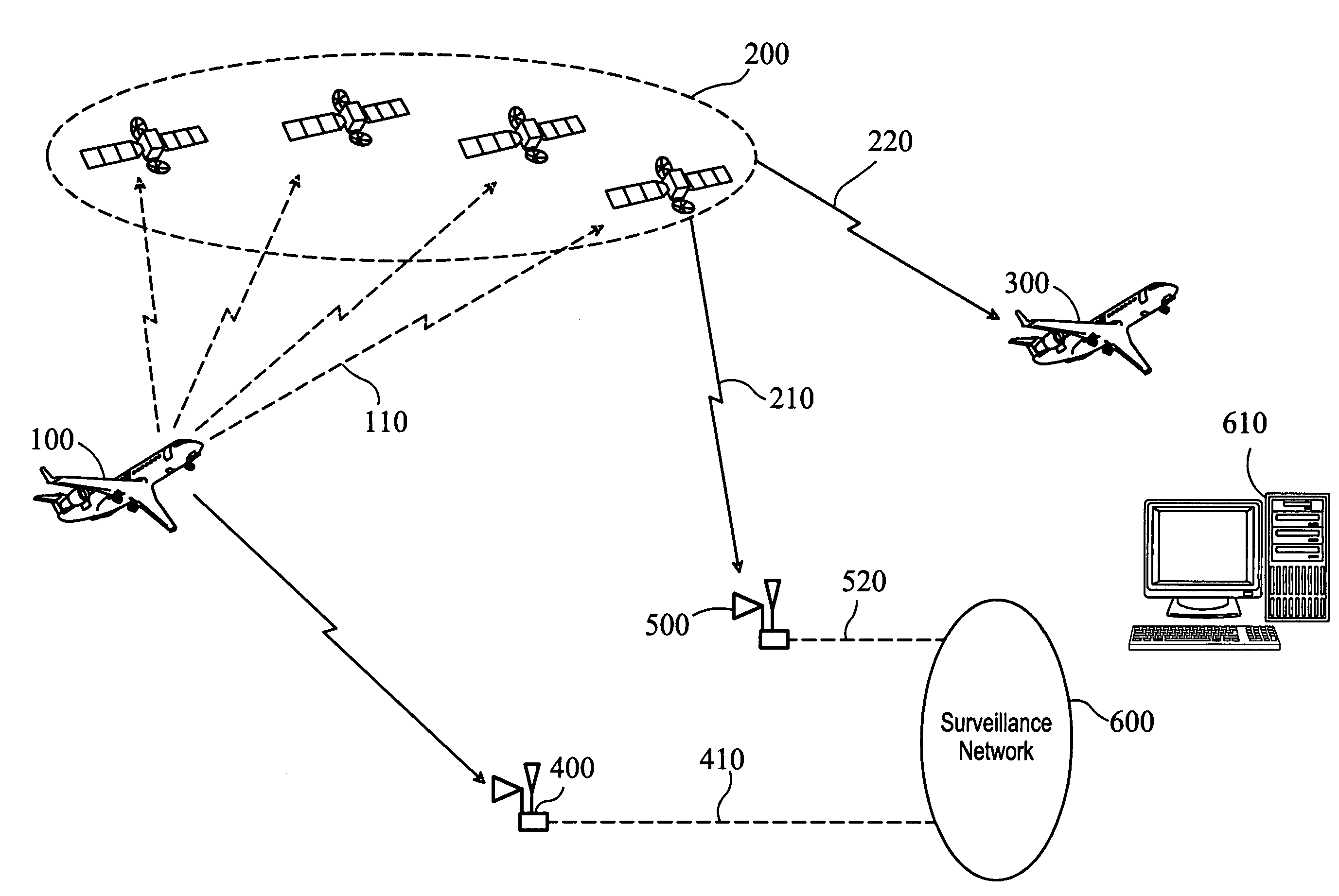
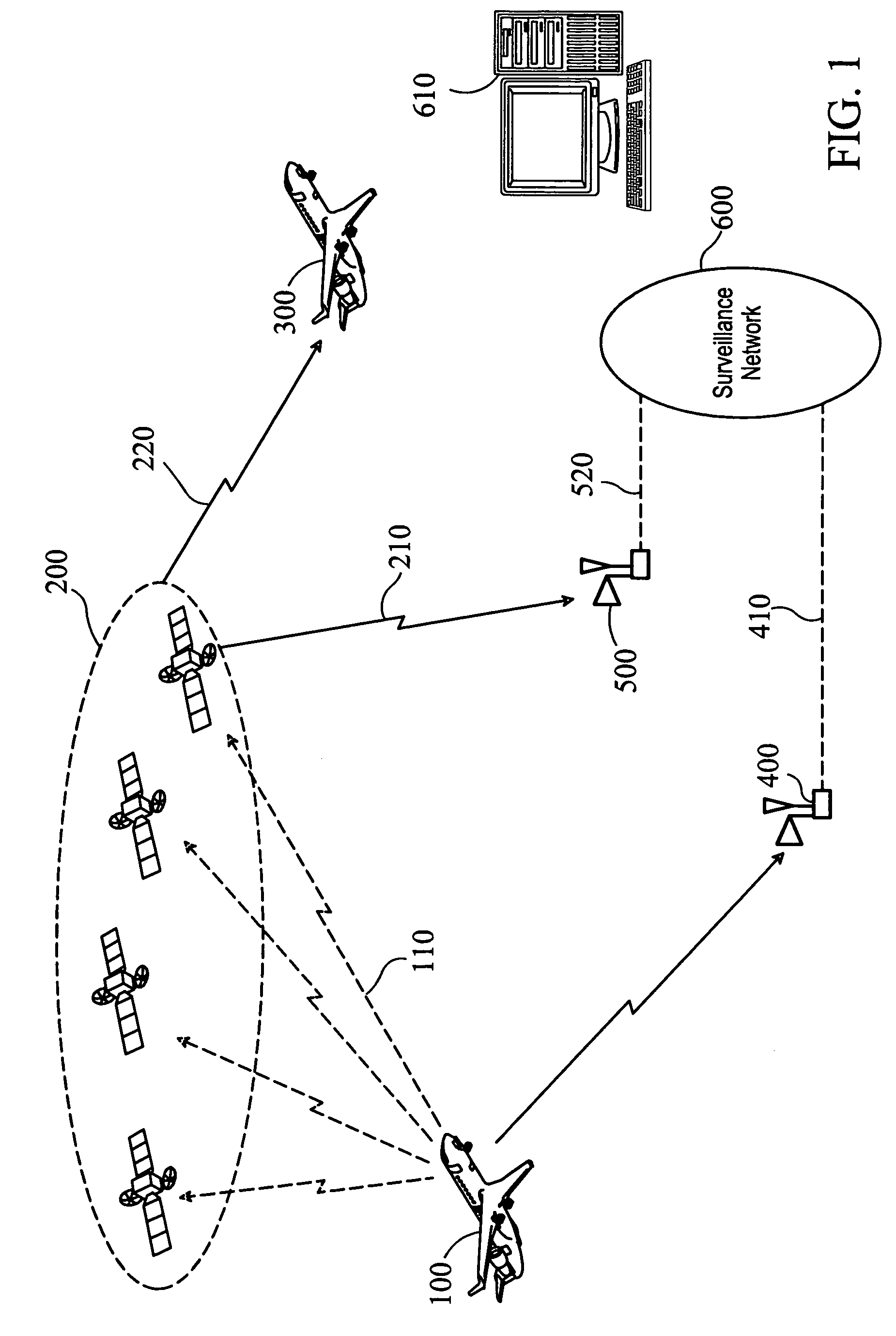
[0038]FIG. 1 is a block diagram of the present invention, illustrating an aircraft 100 emitting various signals, which may include ADS-B, DME, Mode S and various other communications, navigation, and surveillance signals. Aircraft 100 may send self-reported position data to ADS-B receiver 400 which may then communicated the position data 410 to a surveillance network 600. Surveillance network 600 makes available the self-report and independently calculated report to various users 610 where they may be compared and alerts generated in the case of discrepancies. A ground-based station 610 mat then compare self-reported position data with other sources, to determine whether the self-reported position data is accurate.

[0039]Radio signals 110, output from aircraft 100, may also be received by several LEO satellites, and the time-stamped information then used to multilaterate the 3-D geometric position of the aircraft. Multilateration may be performed by the space element (e.g., on one or...

second embodiment

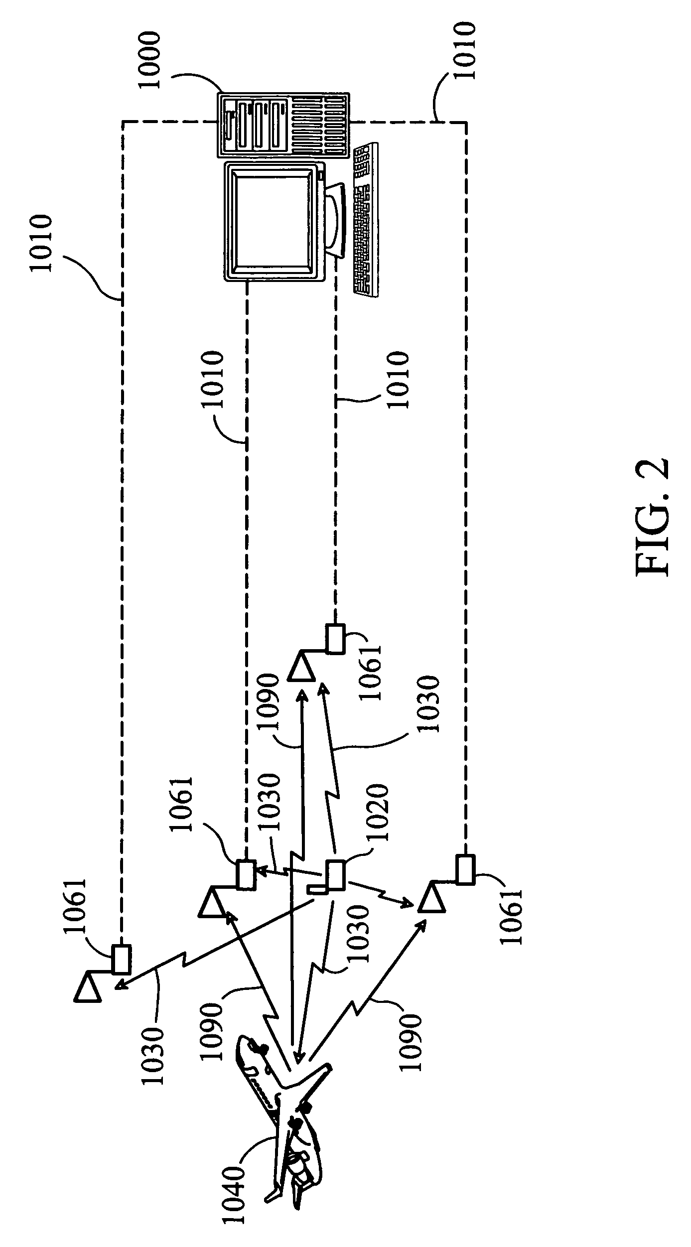
[0041]FIG. 2 is a block diagram illustrating the present invention, illustrating dynamic interrogation. Transmission of interrogation occurs (from interrogator 1020) but time of transmission and position of transmitter are not known and must be determined (1030 MHz Mlat, elliptical ranging, 1090 MHz ADS-B, ADS-C, etc.). Interrogation signal 1030 is received at receivers 1061 and received signals 1010 are sent to central server 1000. Central server may not be physically connected to interrogator 1020 in any way but may be used to compute the position of the interrogator at the time of transmission and the time of transmission.

[0042]Once position and time of transmission of interrogator 1020 has been determined by server 1000, responses from interrogated targets 1040 can be determined through receipt of their response 1090 using the central server to compute position from signals received at receivers 1061.

[0043]Interrogator 1020, targets 1040, and receivers 1061 can be moving or fixe...

third embodiment

[0051]FIG. 4 is a block diagram of this third embodiment of the present invention, illustrating an aircraft 2010 emitting ADS-B signals which are received, time stamped and decoded at receiver 2020 before being passed to the central system processor 2030. The server, knowing the location of the receiver 2020 and the reported position of the aircraft 2010, can calculate the time that the signal originated from the aircraft by calculating and deducting the time taken for the signal to travel from aircraft 2010 to receiver 2020 from the time stamp applied by receiver 2020 when it received the signal.

[0052]Knowing the (fixed) position of receiver 2040, the server can work forward and calculate the time the signal should reach receiver 2040 and compare this time to the time stamp applied by receiver 2040 when the signal actually reaches the receiver.

[0053]If the difference in these two times is outside of a pre determined acceptable level of error, the system can indicate that the data s...


PUM


Abstract

A system and method are disclosed to track aircraft or other vehicles using techniques including multilateration and elliptical surveillance. Unlike conventional approaches that use time difference of arrival for multilateration at a fixed set of reception points, this technique allows targets to be tracked from a number of dynamic or moving reception points. This allows for triangulation / multilateration and elliptical surveillance of targets from combinations of fixed, fixed and moving or only moving ground-based receivers, sea-based receivers, airborne receivers and space-based receivers. Additionally this technique allows for ADS-B validation through data derived from only two receivers to assess the validity and integrity of the aircraft self-reported position by comparing the time of arrival of the emitted message at the second receiver to the predicted time of message arrival at the second receiver based on the self-reported position of the aircraft and the time of arrival at the first receiver. The benefits of using less than three receivers for validation include greater validation coverage areas using a smaller set of ground stations at a lower infrastructure cost.

Description

CROSS-REFERENCE, TO RELATED APPLICATIONS[0001]This application is a Continuation-In-Part of U.S. patent application Ser. No. 11 / 492,711, filed Jul. 25, 2006, and incorporated herein by reference; This application is a Continuation-In-Part of U.S. patent application Ser. No. 11 / 429,926, filed on May 8, 2006, and incorporated herein by reference; This application is a Continuation-In-Part of U.S. patent application Ser. No. 11 / 343,079, filed on Jan. 30, 2006, and incorporated herein by reference; This application is also a Continuation-In-Part of U.S. patent application Ser. No. 11 / 342,289 filed Jan. 28, 2006 and incorporated herein by reference; This application is a Continuation-In-Part of U.S. patent application Ser. No. 11 / 209,030, filed on Aug. 22, 2005, and incorporated herein by reference; This application is a Continuation-In-Part of U.S. patent application Ser. No. 11 / 257,416, filed on Oct. 24, 2005, and incorporated herein by reference; This application is a Continuation-In-...

Claims


Application Information

Patent Timeline
Patent Type & Authority Patents(United States)
IPC IPC(8): G01S3/02G01S11/02G01S13/93
CPCG01S5/0027G01S11/02G01S13/93G01S13/878G01S13/91G01S13/78
Inventor SMITH, ALEXANDER E.HULSTROM, RUSSELLEVERS, CARL A.BREEN, THOMAS J.
Owner ERA AS
Why Eureka
Try Eureka