Solenoid valve for a drop on demand ink jet printer

a technology of ink jet printer and solenoid valve, which is applied in the direction of printers, machines/engines, inking apparatus, etc., to achieve the effects of uniform coloration, increased pile length and closeness, and high viscosity

Inactive Publication Date: 2009-08-11
WILLETT INT
View PDF6 Cites 6 Cited by
  • Summary
  • Abstract
  • Description
  • Claims
  • Application Information

AI Technical Summary

Benefits of technology

[0026]We have found that the use of the specified materials and dimensions for the plunger overcomes many of the problems associated with the use of the conventional stainless steel plunger materials. For example, the conventional materials generate excessive heat energy when reciprocated at frequencies of 1 kHz. The use of materials having high magnetic flux saturation densities enables the plunger of the invention to respond rapidly to changes in the magnetic field generated by the coil without the generation of excessive heat. With the preferred materials, the low coercivity of the plunger material also aids the rapid rise and fall of the induced magnetic field within the plunger under the influence of the field generated as a current is passed through the coil at low applied coil currents. This, preferably coupled with a high relative magnetic permeability of the material, typically greater than 25,000, enables a high magnetic drive force to be generated rapidly between the coil and the plunger. As a result, a plunger of a given size can be accelerated rapidly by the coil by a smaller drive current than a plunger made from conventional materials. This avoids the need to apply high drive currents to the coil, typically in excess of 20 amperes, as hitherto considered necessary. This again reduces the heat energy which is generated as the plunger is moved by the coil. However, it may be possible to use a material of construction which has a coercivity and / or relative magnetic permeability outside the preferred ranges to achieve satisfactory results if the saturation flux density is sufficiently high.
[0093]The ability to hold the valve of the invention in the open position for long periods as described above is of particular advantage in the printing of long pile fabrics where solid blocks of colour are often required. Printing using individual droplets of ink or dye results in an image in which the intensity of the printed image is weaker at the junction of adjacent dots. By holding the valve in the open position, the image is printed as a continuous line of substantially uniform intensity.

Problems solved by technology

As a result, the plungers used hitherto have required substantial magnetic forces to move them and this has required the application of high driving currents to the coils of such solenoids.

Method used


Image

  • Solenoid valve for a drop on demand ink jet printer
  • Solenoid valve for a drop on demand ink jet printer
  • Solenoid valve for a drop on demand ink jet printer

Examples


Embodiment Construction

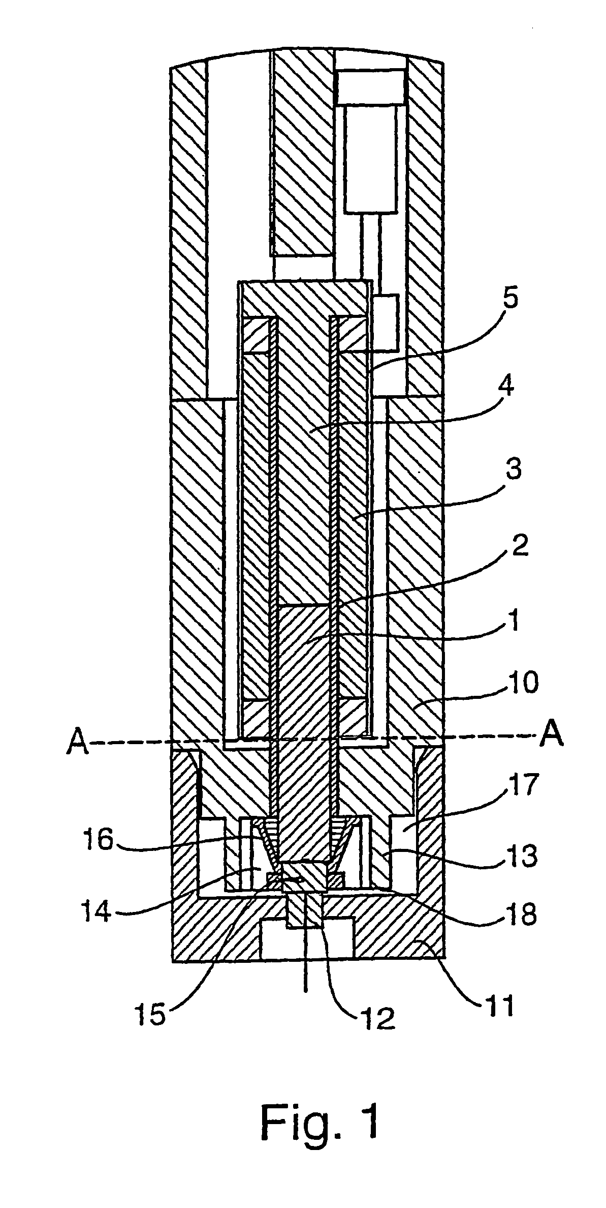
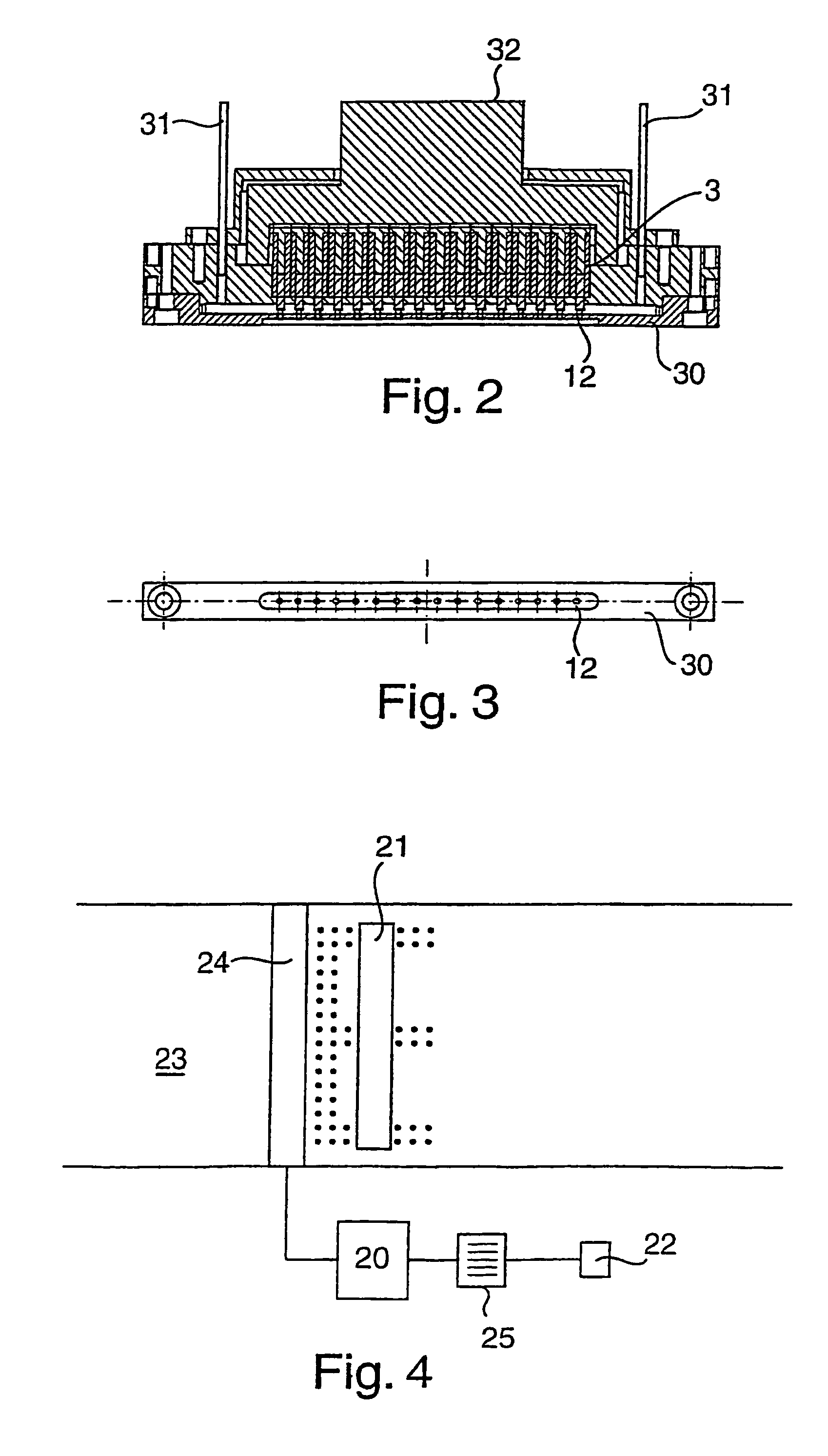
[0108]The valve of FIG. 1 comprises a plunger 1 which is journalled as a close, free sliding fit for axial reciprocation in a stainless steel tube 2. Tube 2 has a thin insulating coating or sleeve (not shown) formed upon its outer face and supports a coil 3 wound upon it. Coil 3 is supplied with an electric current from a source (not shown) under the control of a computer 20, shown in FIG. 4. A stop 4 is mounted at the proximal end of tube 2 to limit the axial retraction of plunger 1 within tube 2. The coil 3 is encased in a metal cylindrical housing 5.

[0109]The above assembly is mounted in a support housing 10 which extends axially beyond the distal end of the coil and has a transverse end wall 11 which carries a jewel nozzle 12. In the embodiment shown in FIG. 1, housing 10 has an axially extending internal annular wall 13 which forms the radial wall of the valve head chamber 14 into which the distal end of the plunger extends. The distal end of the plunger 1 carries a terminal ru...


PUM


Abstract

The invention relates to a solenoid valve made using certain materials which is capable of operation at high frequencies and which can be made as a compact unit. The invention also relates to method for operating a drop on demand ink jet printer incorporating such a valve.

Description

[0001]The present invention relates to a device, notably a high speed solenoid type valve and to an ink jet printer containing such a valve; and to a method of operating an ink jet print head utilising that valve.BACKGROUND TO THE INVENTION[0002]Ink jet printers are non-contact printers in which droplets of ink are ejected from one or more nozzles in a print head. The ejected droplets are projected onto a substrate moving relative to the print head and progressively build up a printed image on the substrate from the dots of ink applied to the substrate. For convenience, the present invention will be described in terms of a substrate which moves with respect to a stationary print head. However, the invention may also be applied to printers in which the print head moves with respect to a stationary substrate. The invention can thus be applied to printers in which the substrate and the print head move relative to one another.[0003]One form of ink jet printer comprises a source of ink u...

Claims


Application Information

Patent Timeline
Patent Type & Authority Patents(United States)
IPC IPC(8): B41J2/04F02M51/00B41J2/00B41J2/175F16K31/06F16K51/00G06K15/10
CPCB41J2/17596F16K31/0655F16K31/0679F16K31/0658B41J2002/041B41J2202/05F16K31/06F16K51/00B41J2/00G06K15/10
Inventor HORSNELL, DAVID ANDREWTOMLIN, MATTHEW BRIANLECHEHEB, AMMARPRIME, OLIVER JOHNFOX, MICHAEL JOHNBATES, CHRISTOPHER MICHAEL
Owner WILLETT INT
Why Eureka
Try Eureka