Eureka AIR delivers breakthrough ideas for toughest innovation challenges, trusted by R&D personnel around the world.

Seal for turbine engine

Inactive Publication Date: 2009-08-11
RAYTHEON TECH CORP
View PDF4 Cites 10 Cited by
  • Summary
  • Abstract
  • Description
  • Claims
  • Application Information

AI Technical Summary

Benefits of technology

[0004]A turbine engine includes a first turbine structure that supports a seal. The seal is movable within a recess of the first turbine structure. The seal is arranged in close proximity to a seal land of a second turbine structure for preventing a fluid from leaking past the seal and seal land. A thermal expansion member interconnects the first turbine structure and the seal. The thermal expansion member expands in response to an increase in temperature to move the seal toward the seal land preventing the typical enlarged gap between the seal and seal land resulting from thermal growth. In one example, the thermal expansion member, which is arranged at each opposing end of a seal segment, is a bimetallic coil spring supported on the first turbine structure by a cage. A free end of the coil spring is secured to the seal at the opposing end portions.

Problems solved by technology

As thermal growth of various components occurs within the turbine engine, the seal moves away from the seal land causing the seal to seal land gap to grow increasing fluid leakage across the seal.

Method used


Image

  • Seal for turbine engine
  • Seal for turbine engine

Examples


Embodiment Construction

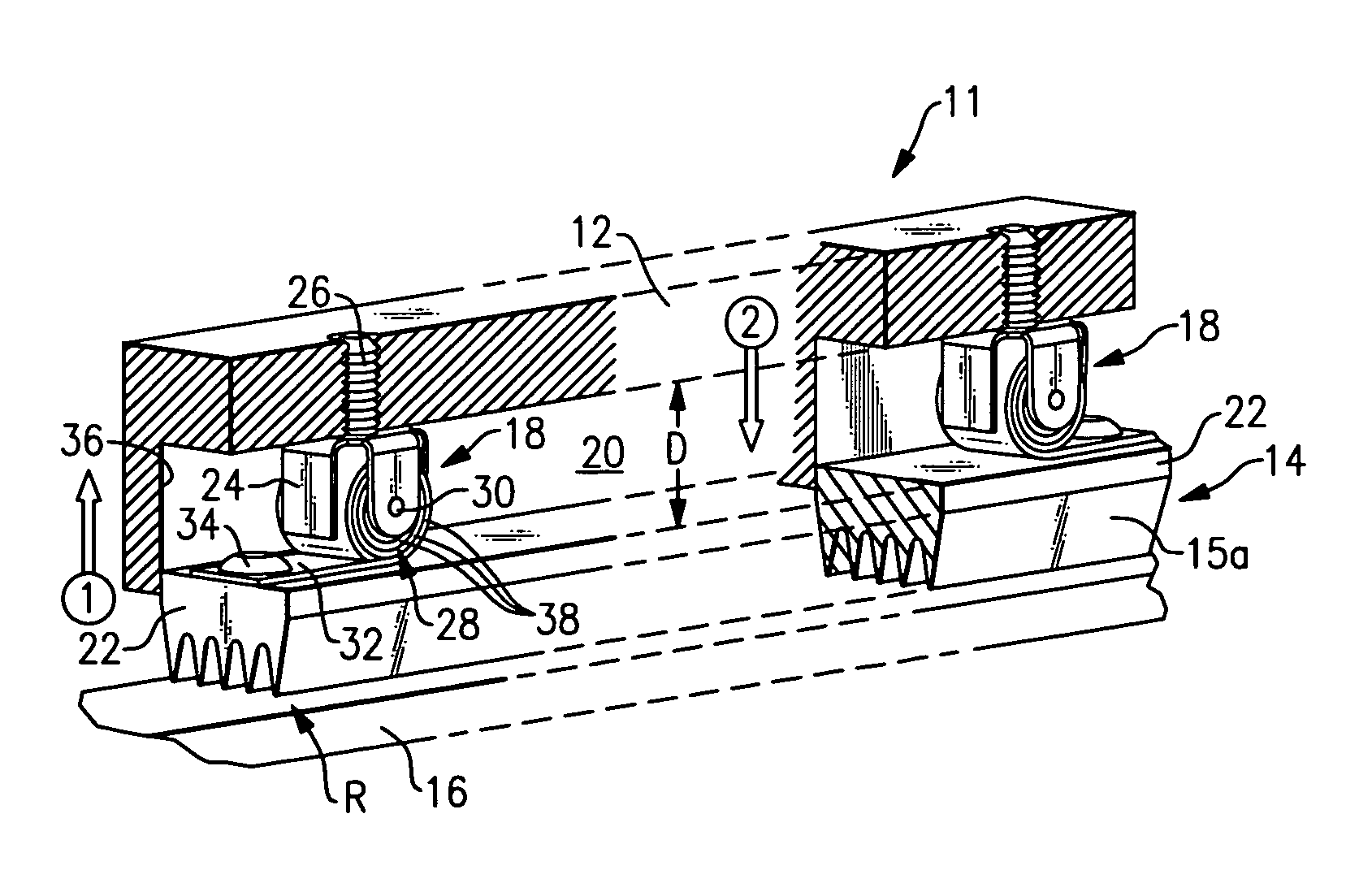
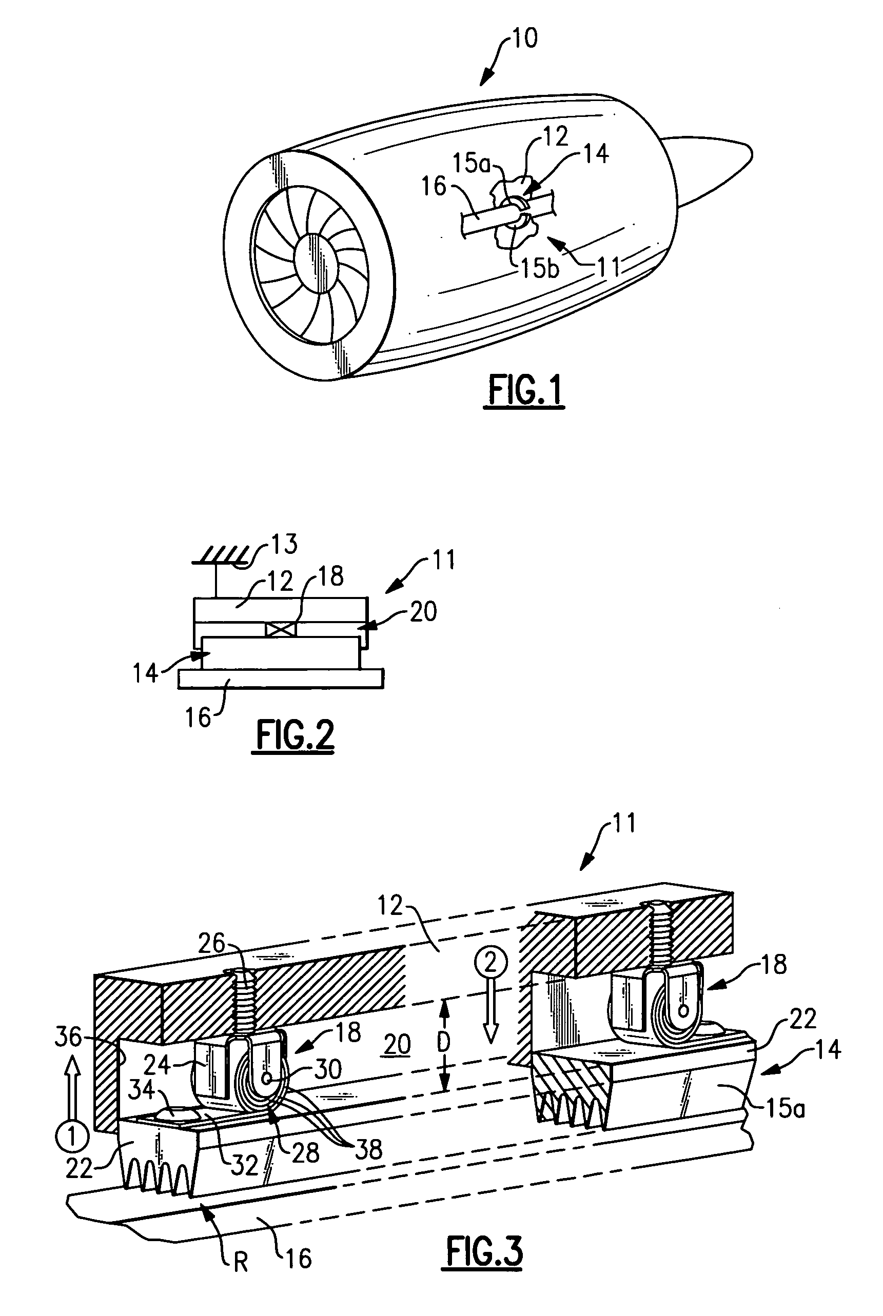
[0010]A turbine engine 10 is schematically shown in FIG. 1. The turbine engine 10 includes a seal arrangement 11 having a support structure 12 such as a housing 13 (shown in FIG. 2). The seal 14 can include two or more segments 15a, 15b that create a seal about a seal land 16 such as a surface of a shaft. Of course, any number of segments can be used. The uniformity of clearance improves when more segments are employed. Of course, the seal 14 can be linear or annular in shape. Furthermore, the seal land 16 can be provided by any static or rotating structure. The seal 14 can be of any suitable type such as an air seal, labyrinth seal, brush seal, knife-edge seal or honeycomb seal.

[0011]Referring to FIG. 2, a thermal expansion member 18 is schematically shown interconnecting the seal 14 to the support structure 12. The seal 14 is permitted to float relative to the support structure 12. A gap 20 is arranged between the seal 14 and support structure 12 to permit the seal 14 to move towa...


PUM


Abstract

A turbine engine includes a first turbine structure that supports a seal. The seal is movable within a recess of the first turbine structure. The seal is arranged in close proximity to a seal land of a second turbine structure for preventing a fluid from leaking past the seal and seal land. A thermal expansion member interconnects the first turbine structure and the seal. The thermal expansion member expands in response to an increase in temperature to move the seal toward the seal land preventing the typical enlarged gap between the seal and seal land resulting from thermal growth. In one example, the thermal expansion member, which is arranged at each opposing end of a seal segment, is a bimetallic coil spring supported on the first turbine structure by a cage. A free end of the coil spring is secured to the seal at the opposing end portions.

Description

BACKGROUND OF THE INVENTION[0001]This invention relates to an air seal that is suitable for use in, for example, a turbine engine.[0002]Various linear and annular seals are used to prevent undesired fluid flow within, for example, a turbine engine. These seals are used to seal static and rotating structures within the engine. Typical types of seals include air seals, labyrinth seals, brush seals, knife-edge seals and honeycomb seals.[0003]A typical seal arrangement within a turbine engine has the seal hard mounted or affixed to a support structure. As thermal growth of various components occurs within the turbine engine, the seal moves away from the seal land causing the seal to seal land gap to grow increasing fluid leakage across the seal. What is needed is a seal that remains in close proximity to the seal land during thermal growth of the turbine engine.SUMMARY OF THE INVENTION[0004]A turbine engine includes a first turbine structure that supports a seal. The seal is movable wit...

Claims


Application Information

Patent Timeline
IPC IPC(8): F01D11/02
CPCF01D11/025Y10S277/931F05D2300/50212
Inventor ADDIS, MARK E.
Owner RAYTHEON TECH CORP
Why Eureka
Eureka Blog
Learn More