Thermal field emission electron gun with reduced arcing

Inactive Publication Date: 2009-08-11
KLA TENCOR CORP
View PDF7 Cites 5 Cited by
  • Summary
  • Abstract
  • Description
  • Claims
  • Application Information

AI Technical Summary

Benefits of technology

[0007]One embodiment relates to a thermal field emission electron gun. The electron gun includes a high-vacuum chamber, a thermal field emission cathode including a filament and tip, a suppressor electrode, an extraction electrode, and a high-voltage power source. The high-voltage power source is coupled to the filament and to the suppressor and extraction electrodes such that the suppressor electrode is

Problems solved by technology

Cathode tip damage by arcing is the most frequent cause of electron gun failure.
Most electron guns returned from the field failed due to arcing well before exhaustion of the potential lifetime of the gun.
In practice, the useful lifetimes of such electro

Method used


Image

  • Thermal field emission electron gun with reduced arcing
  • Thermal field emission electron gun with reduced arcing
  • Thermal field emission electron gun with reduced arcing

Examples


Embodiment Construction

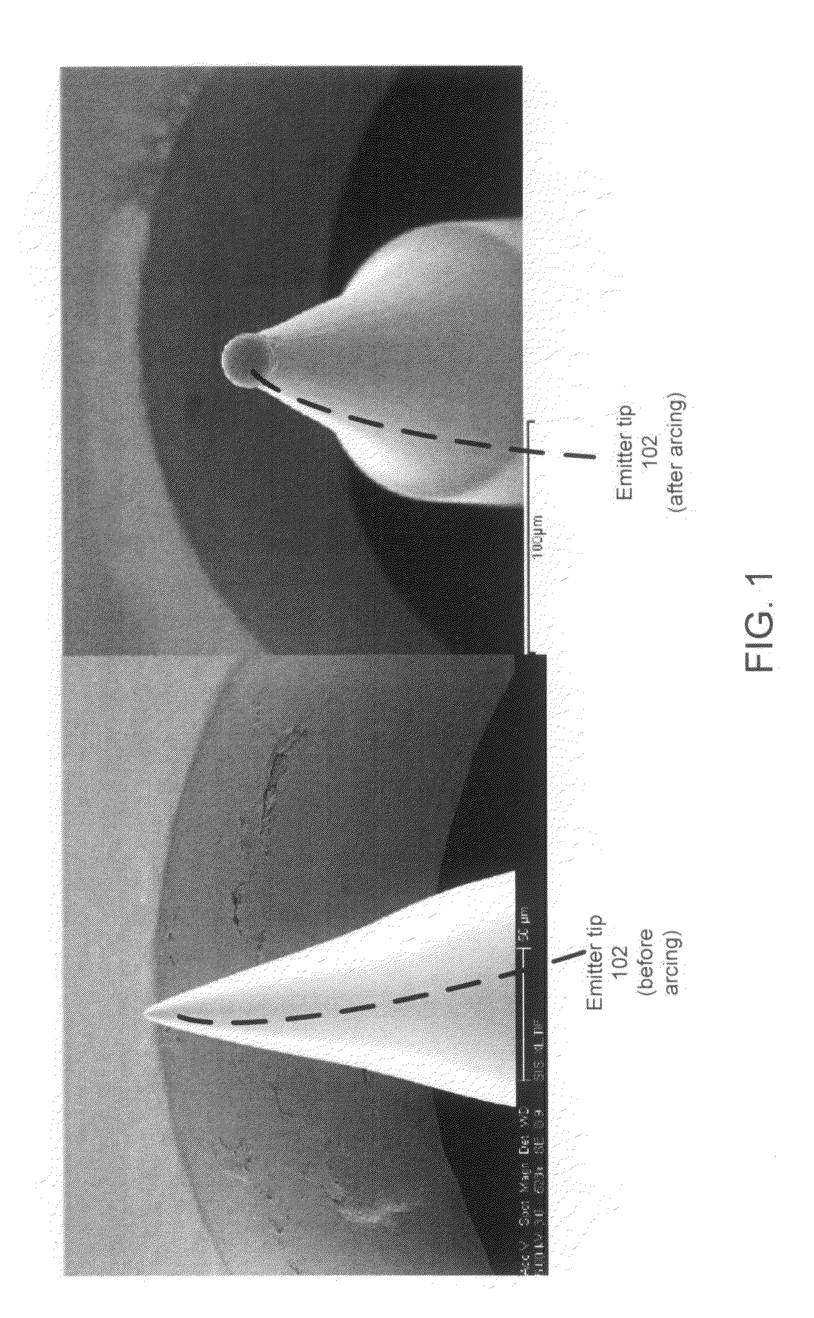
[0015]FIG. 1 is a photomicrograph showing an actual emitter tip 102 which has been damaged due to arcing caused melting at the apex of the tip. As shown, the apex of the tip is no longer sharp after being melted. As discussed herein, such melting of the apex of the emitter tip is typically caused by arcing between the emitter tip and the extractor electrode and results in the need to replace the emitter tip.

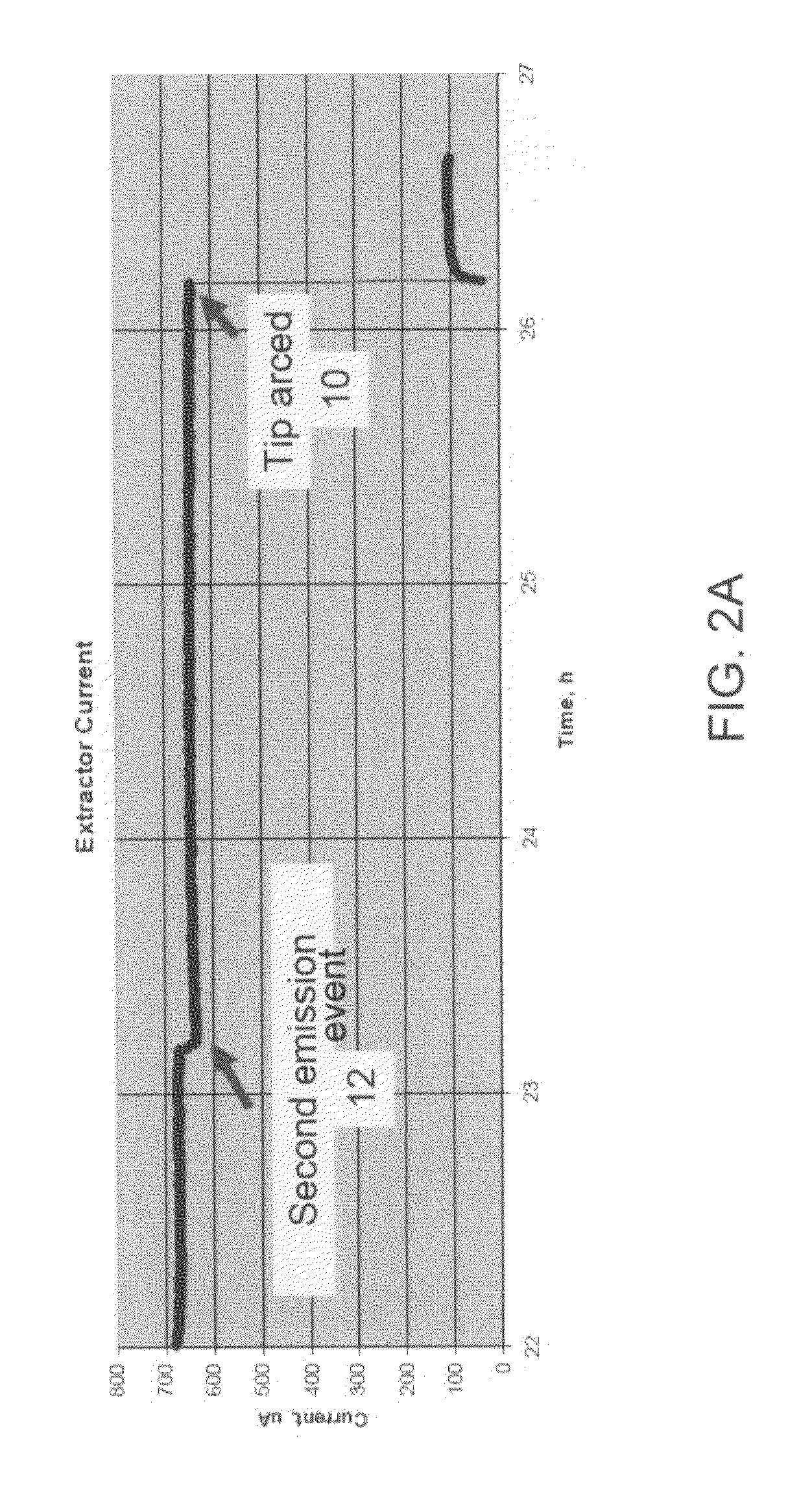
[0016]FIG. 2A is a graph showing observed extractor current versus time during a time period including a tip arcing event for a conventional thermal field emission gun. As shown, in this particular example, there is a dramatic drop in extractor current after 26 hours of operation. In this particular example, the extractor current drops from about 650 microamperes to about 100 microamperes. Applicant has identified this drop with an emitter tip arcing event 10. After the tip arcing 10 (the main arcing event), the apex of the emitter tip is melted, and so the emitter typically need...


PUM


Abstract

One embodiment relates to a thermal field emission electron gun. The electron gun includes a high-vacuum chamber, a thermal field emission cathode including a filament and a tip, a suppressor electrode, an extraction electrode, and a high-voltage power source. The high-voltage power source is coupled to the filament and to the suppressor and extraction electrodes such that the suppressor electrode is at a negative voltage potential in relation to the filament and the extraction electrode is at a positive voltage potential in relation to the filament. A current-limiting resistor is electrically coupled in series with the suppressor electrode. Applicant has determined that such a current-limiting resistor substantially reduces undesirable discharges and improve the reliability and lifetime of the electron gun. Other embodiments, aspects and features are also disclosed.

Description

BACKGROUND OF THE INVENTION[0001]1. Technical Field[0002]The present disclosure relates to thermal field emission electron guns and methods for making and using same.[0003]2. Description of the Background Art[0004]A thermal field emission electron gun comprises an emitter tip that is heated by electric current and has applied electric field causing emission of electrons from the tip. Such an electron gun may be used in scanning electron microscopes and other similar instrumentation.[0005]Cathode tip damage by arcing is the most frequent cause of electron gun failure. Arc events may occur during manufacture of the electron gun, during the first few weeks of field application of the electron gun, as well as during the rest of its operational lifetime. Most electron guns returned from the field failed due to arcing well before exhaustion of the potential lifetime of the gun. In practice, the useful lifetimes of such electron guns are typically limited by arcing from the emitter tip. Th...

Claims


Application Information

Patent Timeline
IPC IPC(8): H01J37/141
CPCH01J37/065H01J37/073H01J37/28H01J2237/06341H01J2237/0206
Inventor CHUBUN, NIKOLAI N.
Owner KLA TENCOR CORP
Why Eureka
Try Eureka