Communication cable assembly and installation method

a technology of communication cable and assembly method, which is applied in the field of cable assembly, can solve the problems of difficult to pass such a cable assembly, not an advisable technique, etc., and achieve the effect of preventing damage to the connecting element and/or the optical fiber and simple mechanical operation

Active Publication Date: 2009-08-11
DRAKA COMTEQ BV
View PDF20 Cites 83 Cited by
  • Summary
  • Abstract
  • Description
  • Claims
  • Application Information

AI Technical Summary

Benefits of technology

[0008]Thus, the communication connector can be connected in communicative contact to the optical fiber by way of a simple mechanical operation after the cable assembly has been led to the end position. No complex and costly finishing operations (e.g., polishing) need to be carried out at the end user's location.
[0009]According to a further aspect of the invention, the cable assembly embraces a spring element that may be positioned around the optical fiber between the connecting element and the cable sheath(s). The spring element may be retained by the connecting element and a retaining sleeve arranged around the optical fiber. In this way, any loads exerted on the end faces of an optical fiber and the connecting element can be absorbed by the compression of the spring element, thus preventing damage to the connecting element and / or the optical fiber.
[0011]According to the invention, to make it easier to pass the cable assembly through the cable guide, the connecting element and the spring element may be protected by a protective element that is removal positioned at the free end of the communication cable.
[0026]This facilitates the collection of the free, front end of the communication cable assembly when it is guided through the cable guide with the aid of a transfer medium (e.g., gas or liquid). More particularly, the enclosure is configured as a tube-shaped element having a first and second open end, wherein the first open end is provided with a collar-shaped clamp for coupling with the end position of the cable guide. This allows a quick and secure coupling and uncoupling of the device to the cable guide at the premises of the end user (i.e., where the cable assembly is to be installed).

Problems solved by technology

This is not an advisable technique, however, because it is necessary to expose the optical fiber by removing the cable sheath, to mount the exposed optical fiber end in the connector, and to polish the end face of the optical fiber so as to enable a good signal transmission.
In addition, it is difficult to pass such a cable assembly (i.e., having a complete connector mounted to the free, front end of the communication cable) through the cable guide.
This makes it necessary to carry out operations at the end position (e.g., in the end user's home), which is undesirable in view of the extent of planning and the man-hours involved.

Method used


Image

  • Communication cable assembly and installation method
  • Communication cable assembly and installation method
  • Communication cable assembly and installation method

Examples


Embodiment Construction

[0040]The present invention is described herein with reference to the accompanying drawings. As will be appreciated by those having ordinary skill in the art, these drawings are schematic representations, which are not necessarily drawn to scale. This invention may be embodied in many different forms and should not be construed as limited to the embodiments set forth herein. The embodiments disclosed are provided to convey the scope of the invention to those having ordinary skill in the relevant art. In this regard, like parts will be indicated by the same numerals in the accompanying drawings and following description.

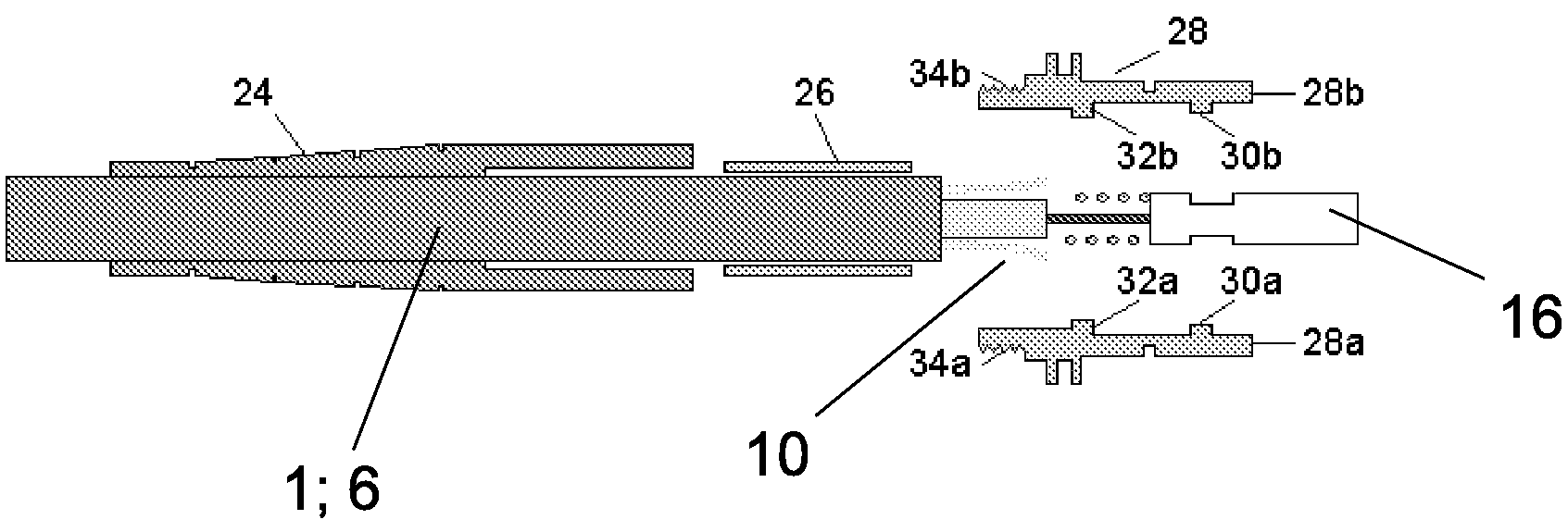
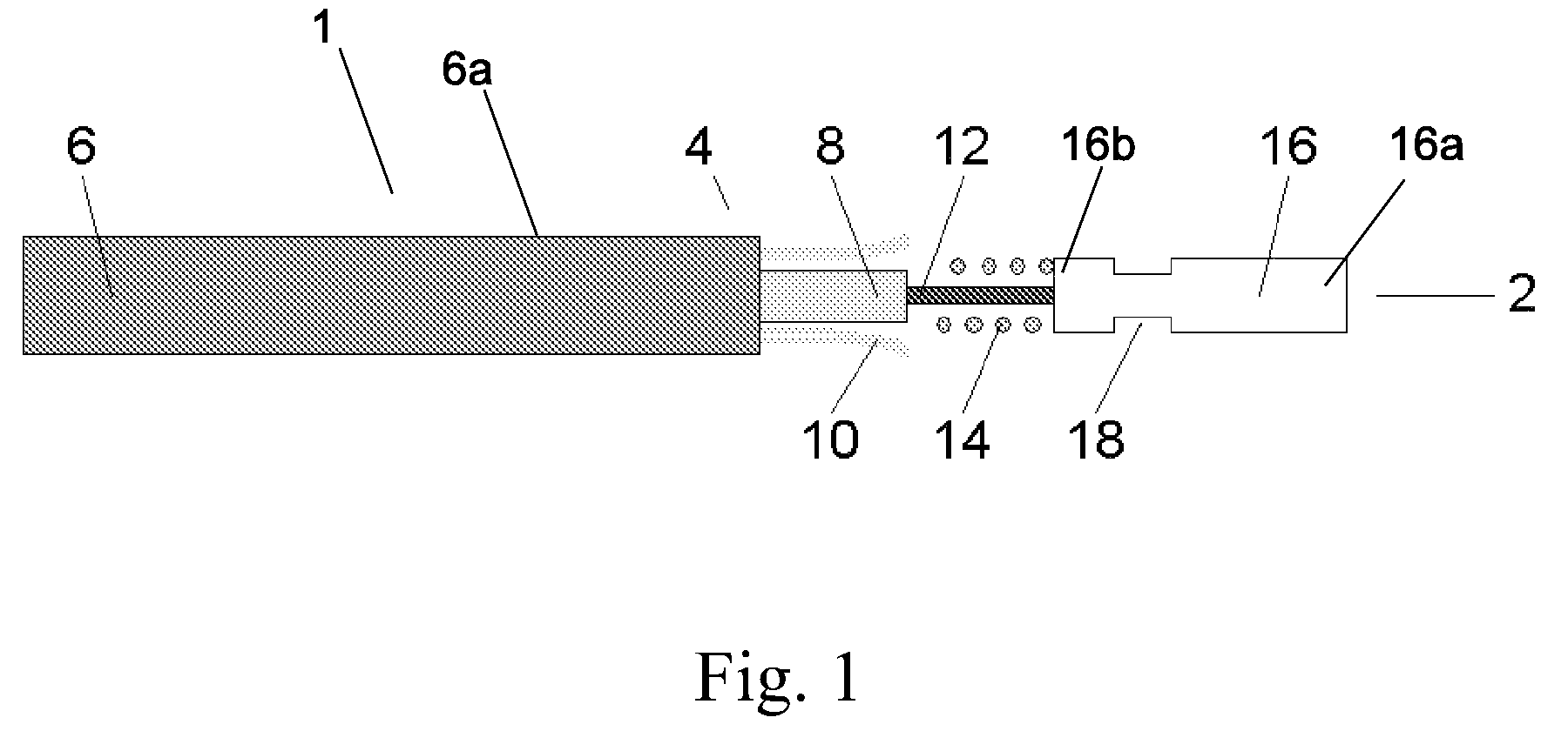
[0041]FIG. 1 depicts a first embodiment of the communication cable assembly 1 according to the present invention. The cable assembly 1 is built up of a communication cable 6 that has a free, front end 4. The communication cable 6 can be passed through a cable guide (not shown) to an end position via its free end 4.

[0042]The communication cable 6 includes at least an o...


PUM


Abstract

The invention relates to a cable assembly for communication purposes. The cable assembly includes a communication cable having a free, front end and a communication connector. The communication cable can be passed through a cable guide from a starting position to an end position with its free, front end. The communication cable includes at least one optical fiber that is coaxially surrounded by at least one cable sheath, within which at least one strain-relieving element is present. The communication connector can be mounted to the free end of the communication cable in communicative contact with the optical fiber.To make it possible to pass the communication cable through the cable guide, the optical fiber is exposed at the communication cable's free, front end, which is fixedly surrounded by a connecting element. The connecting element can be mechanically connected to the communication connector after the communication cable has passed through the cable guide.Thus, the communication connector can be connected in communicative contact to the optical fiber by way of a simple mechanical operation after the cable assembly has been led to the end position. Complex and costly finishing operations need not be carried out at the end user's location.

Description

CROSS-REFERENCE TO PRIORITY APPLICATION[0001]This application hereby claims the benefit of pending Dutch Application No. 1,031,792 (filed May 11, 2006 at the Dutch Patent Office), which is hereby incorporated by reference in its entirety.FIELD OF THE INVENTION[0002]The invention relates to a cable assembly for communication purposes. The cable assembly includes a communication cable having a free, front end and a communication connector. The communication cable can be passed through a cable guide from a starting position to an end position with its free, front end. The communication cable includes at least one optical fiber that is coaxially surrounded by at least one cable sheath, within which at least one strain-relieving element is present. The communication connector can be mounted to the free end of the communication cable in communicative contact with the optical fiber.BACKGROUND OF THE INVENTION[0003]When optical fiber networks are installed, the network includes several conn...

Claims


Application Information

Patent Timeline
Patent Type & Authority Patents(United States)
IPC IPC(8): G02B6/00G02B6/36
CPCG02B6/3887G02B6/4464G02B6/3888G02B6/38875G02B6/3889G02B6/52
Inventor LOCK, PIETERGRIFFIOEN, WILLEM
Owner DRAKA COMTEQ BV
Why Eureka
Try Eureka