Full-automatic mold replacing trolley system

A mold trolley, fully automatic technology, applied in conveyor control devices, conveyor objects, conveyors, etc., can solve the problems of abnormally frequent mold change of the press, high labor intensity of operators, and low mold change efficiency. Achieve the effect of improving equipment utilization, reducing labor intensity of workers, and reducing space occupied

Active Publication Date: 2016-03-23
NINGBO YIJIE PRECISION MACHINERY CO LTD
View PDF6 Cites 5 Cited by
  • Summary
  • Abstract
  • Description
  • Claims
  • Application Information

AI Technical Summary

Problems solved by technology

[0002] Molds are widely used in all aspects of the mechanical field. At present, when changing large-scale molds in the production workshop, forklifts are generally used to change molds, or driving is used to place the molds on the mold changing trolley, and then the molds are changed. The range of motion is large. It takes up a lot of space; small molds are generally replaced manually
In the production process, due to the many types of parts produced by the mold, there are many types of molds used. Using the existing mold changing method, the mold changing work of the press will be abnormally frequent, and the mold changing efficiency is low and takes up space. Large, labor-intensive operators, long mold change time

Method used


Image

  • Full-automatic mold replacing trolley system
  • Full-automatic mold replacing trolley system
  • Full-automatic mold replacing trolley system

Examples


Embodiment 1

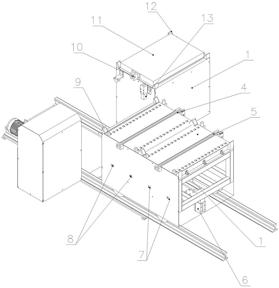
[0019] State before implementation: there is mold A on machine device 1, no mold in area A, and mold B in area B;

[0020] Implementation content, change the mold B in area B to machine device 1, the specific steps are as follows:

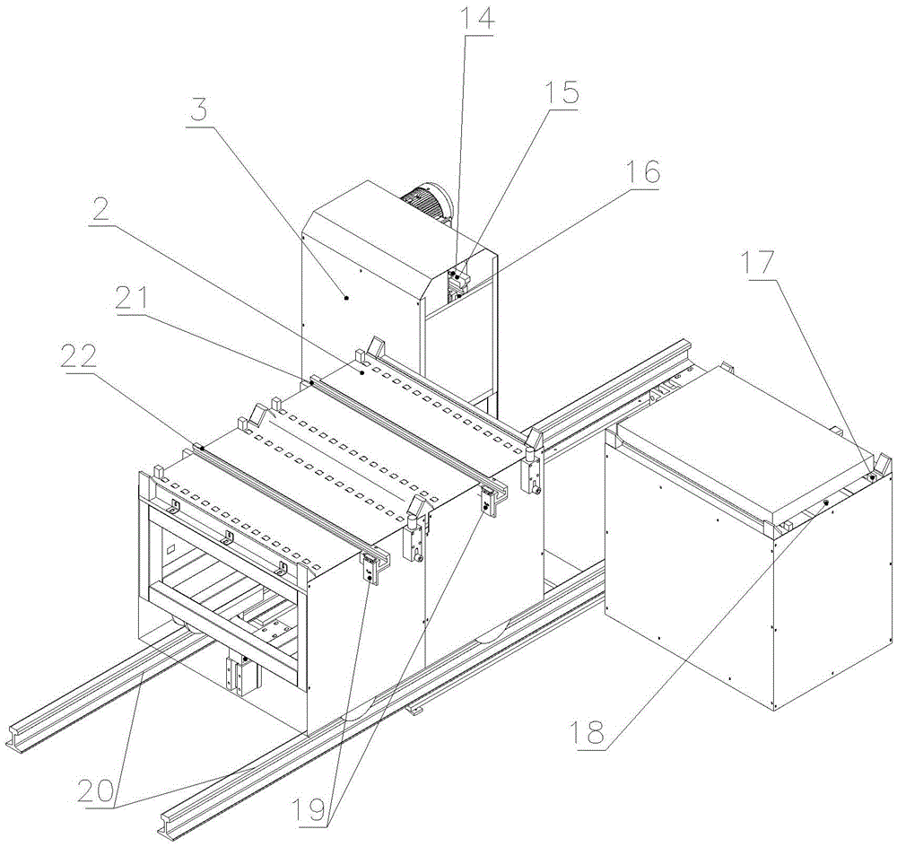
[0021] (1) Press the start button, the module detector 18 detects that there is a mold on the machine, the lower cylinder 6 of the trolley retracts, the upper proximity switch on the lower cylinder 6 of the trolley has a signal, the indicator light is on, and the trolley device 2 starts , the trolley moves forward;

[0022] (2) The detector three left 8 receives the signal, the indicator light is on, the trolley device 2 starts to decelerate and arrives at the designated position, the T slot 21 in the A area on the trolley device 2 is aligned with the push-pull T slot 16 on the push-pull mechanism 3, The bottom cylinder 6 of the backstage car stretches out in 1 second, and the trolley device 2 is fixed, and the lower proximity switch on the bottom...

Embodiment 2

[0029] State before implementation: there is mold A on machine device 1, mold B in area A, and no mold in area B;

[0030] Implementation content, change the mold B to the machine device 1, the specific steps are as follows:

[0031] (1) Press the start button, the module detector 18 detects that there is a mold on the machine, the lower cylinder 6 of the trolley retracts, the upper proximity switch on the lower cylinder 6 of the trolley has a signal, the indicator light is on, and the trolley device 2 starts , the trolley moves forward;

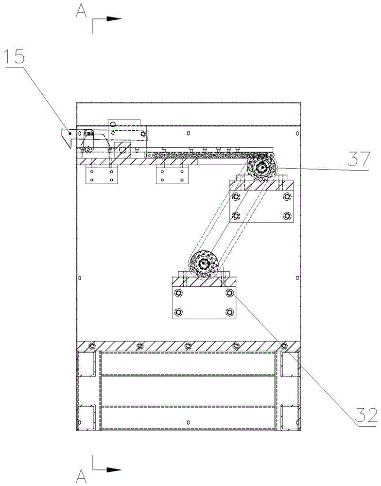
[0032] (2) The detector three right 7 receives the signal, the indicator light is on, the trolley arrives at the designated position, the T slot 22 in area B is aligned with the push-pull T slot 16, and the lower cylinder 6 of the backstage trolley extends out in 1 second, and the trolley device 2 is fixed. The lower proximity switch on the bottom cylinder 6 of the trolley has a signal, and the indicator light is on, and the hook 15 advance...

Embodiment 3

[0039] State before implementation: There is no mold on machine device 1, there is mold A in area A, and mold B in area B;

[0040] Implementation content, change the mold A to the machine device 1, the specific steps are as follows:

[0041] (1) Press the start button, the module detector 18 has no signal, the lower cylinder 6 of the trolley retracts, the upper proximity switch on the lower cylinder 6 of the trolley has a signal, the indicator light is on, the trolley device 2 starts, and the trolley moves forward ;

[0042] (2) The detector three left 8 receives the signal, the indicator light is on, the trolley device 2 starts to decelerate and arrives at the designated position, the T slot 21 in the A area on the trolley device 2 is aligned with the push-pull T slot 16 on the push-pull mechanism 3, 1 second, the lower cylinder 6 of the backstage car stretches out, the trolley device 2 is fixed, the lower proximity switch on the lower cylinder 6 of the trolley has a signal...


PUM


Abstract

The invention discloses a full-automatic mold replacing trolley system. The full-automatic mold replacing trolley system comprises a machine platform device, a trolley device, a push-pull device and a track, wherein the trolley device is mounted on the track; the machine platform device and the push-pull device are symmetrically positioned at the two sides of the track; an area A and an area B which are the same in size are arranged in parallel at the upper end of the trolley device; a left detector III and a right detector III are also mounted at the side surface of the trolley device; the push-pull device is provided with a power source motor, a driving system, a hook detector, a hook, a push-pull T-shaped groove and a hook base, wherein the hook is mounted in the push-pull T-shaped groove by the hook base; the hook detector is arranged at one side of the hook. By using a mechanical structure to replace manual operation and the original large machinery operation, the full-automatic mold replacing trolley system disclosed by the invention has the advantages of saving the operation space, shortening the working time, alleviating the labor strength of a worker, guaranteeing the operation safety of the worker and improving the work efficiency.

Description

technical field [0001] The invention relates to equipment, in particular to a fully automatic mold changing trolley system. Background technique [0002] Molds are widely used in all aspects of the mechanical field. At present, when changing large-scale molds in the production workshop, forklifts are generally used to change molds, or driving is used to place the molds on the mold changing trolley, and then the molds are changed. The range of motion is large. It takes up a lot of space; small molds are generally replaced manually. In the production process, due to the many types of parts produced by the mold, there are many types of molds used. Using the existing mold changing method, the mold changing work of the press will be abnormally frequent, and the mold changing efficiency is low and takes up space. Large, the labor intensity of the operator is high, and the mold change time is long. Therefore, how to improve the mold changing efficiency of the mold is an urgent pr...

Claims


Application Information

Patent Timeline
Patent Type & Authority Applications(China)
IPC IPC(8): B65G35/00B65G43/00
CPCB65G35/00B65G43/00
Inventor 王德臣
Owner NINGBO YIJIE PRECISION MACHINERY CO LTD
Why Eureka
Try Eureka