
Brush wheel typed nebulizer

a brush wheel and nebulizer technology, applied in the field of nebulizers, can solve the problems of large restrictions in the range and performance of liquid nebulization, failure and inability to achieve atomization

Inactive Publication Date: 2015-02-24
CHEN WEN PIN +1
View PDF7 Cites 4 Cited by
  • Summary
  • Abstract
  • Description
  • Claims
  • Application Information

AI Technical Summary

Benefits of technology

[0010]To resolve the drawbacks as previously set forth, the major objectives of the present invention are to provide a brush wheel typed nebulizer suitable for highly viscous liquids which can cast off the limits caused by conventional nebulization methods and structures, thus reducing the efficiency losses generated by complicated electric energy conversions and simplifying the adopted mechanical operations in order to achieve the objectives of smaller size, low energy consumption and high nebulization performance and feasibility for handheld devices, thereby overcoming the difficulties found in existing technologies.
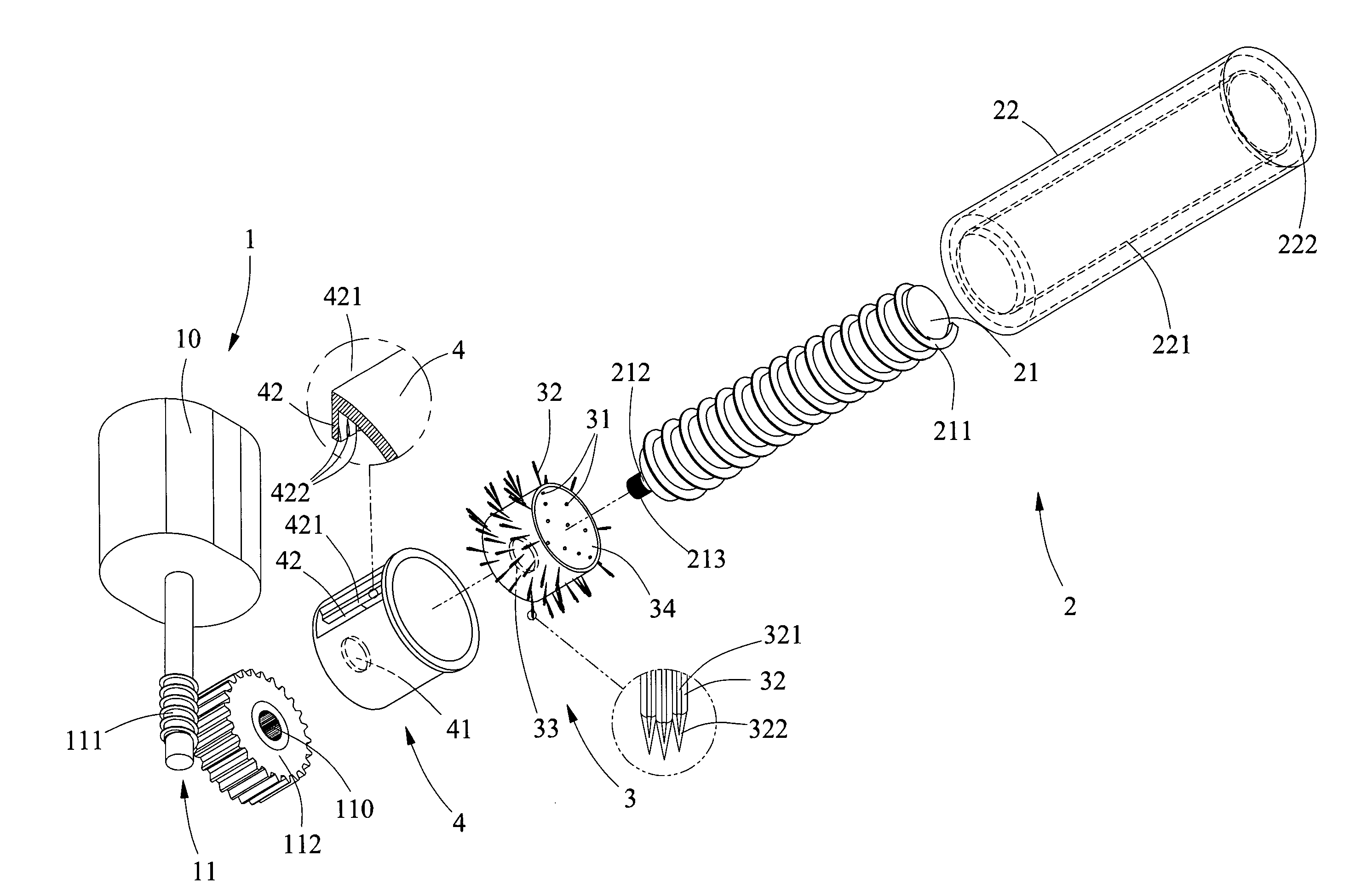
[0023]With the disclosed design, the present invention allows to draw the liquid through the spiral pump to the brush wheel and provides a suitable pressure to squeeze the liquid out of the brush wheel from the aperture of the implant hole in the brush wheel along the ditch on the brush hair, in which an interferential impeding and strong centrifugal force can be generated by means of the elastic brush hairs in the brush wheel and the inner bulge on the notch of the sleeve lid, so as to fling off the liquid attached on the brush hair thereby enabling a nebulizer device applicable for highly viscous liquids featuring the atomized liquid ejection of extremely fine microdrops.

Problems solved by technology

The devices for successfully achieving liquid nebulization effects, as described in the disclosures of U.S. Pat. Nos. 6,357,671, 7,467,786, 6,152,383 and 7,347,889, the structures thereof are not only complicated, and the configurations of such internal circuits as well as components cause significant difficulties in maintenance and examination processes, and also the devices themselves may only work on liquids of no or low viscosity, but become completely inoperable for highly viscous liquids with gravity effect.
It can be concluded that, due to such incapability for highly viscous liquids, prior art products can work only on water or water-based liquids; but, for oleaginous fluids having high viscosity and strong adhesive force, they may fail in effect.
However, if the water is substituted by oleaginous fluids, then the energy from conventional supersonic wave vibration is not able to break the bond between oil molecules to generate such cavities, so the atomization effect can not be achieved.
As such, the applicable ranges and performances of liquid nebulization are greatly restricted.
Since such a supersonic wave vibration approach is ineffective for highly viscous liquids due to the factor of surface tension, the atomization operation may fail so that its feasibility and utilization are significantly reduced.
However, such a product applies the battery-enabled switching converter to convert high voltage electrostatics, then destroys the surface tension of the liquid power foundation by means of high potential difference, and subsequently blows power foundation microdrops out of a nozzle by using electrostatic-generated anion airflows thereby acquiring the desired atomization effect.
Unfortunately, electric shock events did frequently occur in users because of high voltage electrostatics used in this product for operations, so the government of United States issued the sales prohibition order and this product was accordingly rejected by consumers.
Without any new nebulizer substations providing safer and more efficient aspects, the beauty and cosmetics consumer market is so far in a sort of vacuum state, thus leading to great inconvenience for consumers.

Method used


Image

  • Brush wheel typed nebulizer
  • Brush wheel typed nebulizer
  • Brush wheel typed nebulizer

Examples


Embodiment Construction

[0032]To facilitate thorough appreciation of features, contents and advantages of the present invention as well as effects the present invention is capable of, the present invention is hereunder illustrated in details by means of embodiments with reference to appended drawings. However, the drawings referred by the present disclosure are essentially for the purpose of exemplary and auxiliary descriptions, not necessarily presenting the actual ratios and precise allocations utilized in implementing the present invention. It should be noticed, consequently, that the scope of actual implementations according to the present invention is not to be restricted by such ratio and allocation relationships depicted in the appended diagrams.

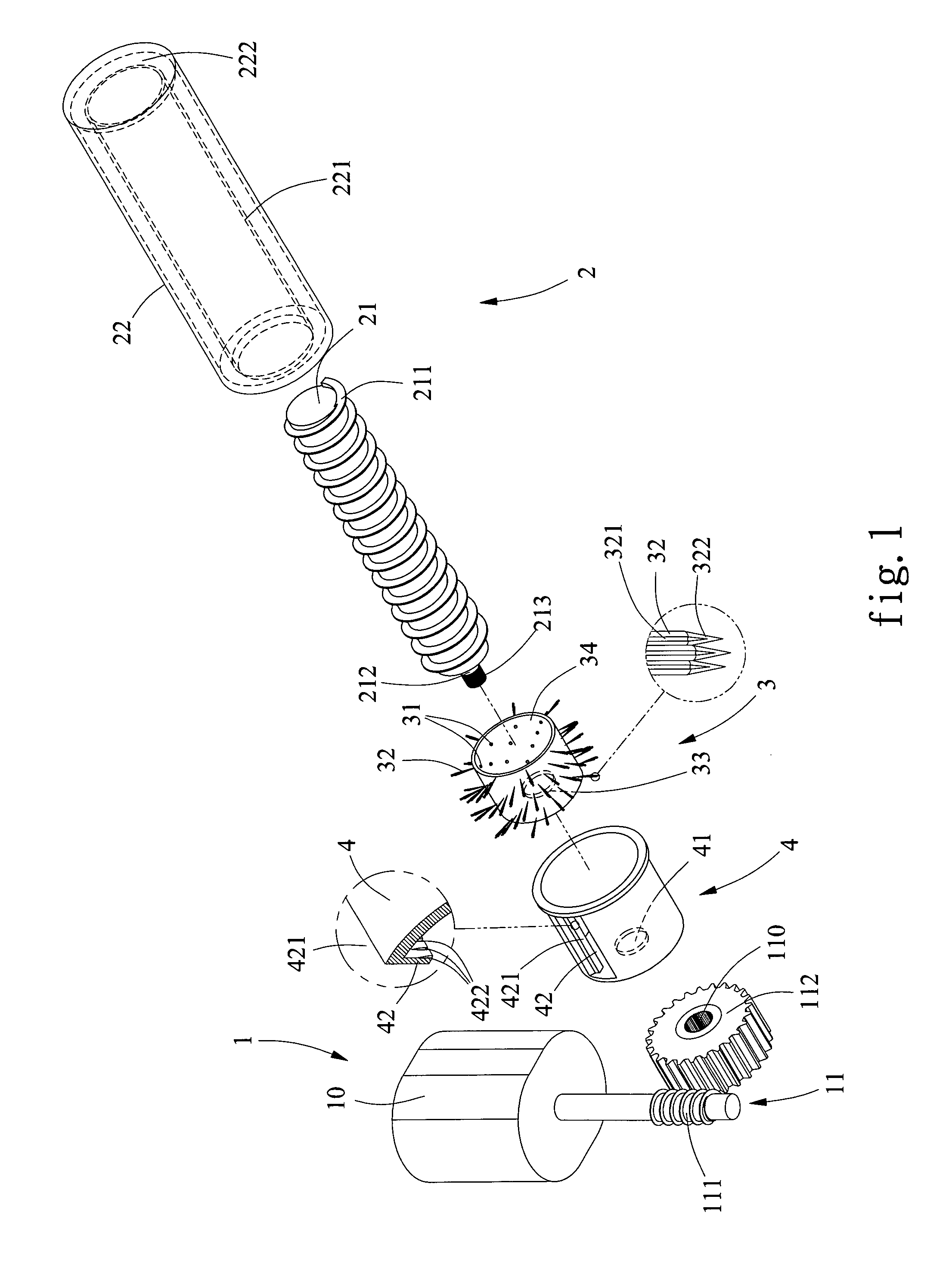
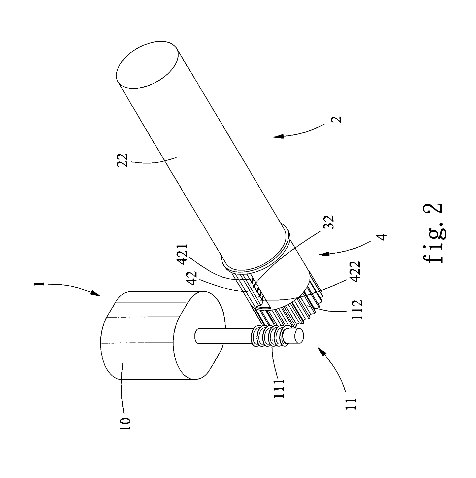
[0033]Referring initially to FIGS. 1, 2 and 3, a stereo disassembly view, a stereo assembly view as well as an assembly cross-section view of the present invention are respectively shown, wherein the brush wheel typed nebulizer in a preferred embodiment acco...


PUM


Abstract

The present invention provides a brush wheel typed nebulizer, comprising: a drive device; a spiral pump, including a body, an outer sleeve, in which the outer periphery of the body is installed with at least a helicoid member closely attached to an inner sleeve having a flow opening inside the outer sleeve; a brush wheel, configured with multiple implant holes and having brush hairs forming at least a ditch; a sleeve lid, on which a notch is configured in correspondence with the end of the brush hair, and an inner bulge acting conjunctively with the end of the brush hair and having multiple guide grooves. With such a design, it is possible to fling off the highly viscous liquid attached on the brush hair to create atomized liquid of extremely tiny microdrops.

Description

BACKGROUND OF THE INVENTION[0001]1. Field of the Invention[0002]The present invention generally relates to a nebulizer; in particular, it relates to a brush wheel typed nebulizer suitable for liquid of high viscosity, in which an end of the spiral pump is configured fixedly in wrap with a brush wheel, and the brush wheel is implanted with brush hairs having at least a ditch. The brush hair along with the sleeve lid exteriorly installed and having the notch and the inner bulge can together create an interferential obstruction, so that it is possible to further allow the brush hair to generate a strong centrifugal force in order to fling off the liquid attached on the brush hair thereby obtaining extremely tiny microdrops.[0003]2. Description of Related Art[0004]Nebulizers have been long comprehensively applied in various fields of our daily lives; from wetting, fragrance, landscaping equipments in civil utilizations, atomizing inhalation treatment devices for medical purpose, thermal...

Claims


Application Information

Patent Timeline
Patent Type & Authority Patents(United States)
IPC IPC(8): B05B3/08B05B9/08
CPCB05B3/08B05B9/0866
Inventor CHEN, WEN-PINTUNG, CHIU-YUEH
Owner CHEN WEN PIN
Learn More