Flow path switching valve, high performance liquid chromatography using the same and analytical method thereof

a technology of flow path switching valve and high-performance liquid chromatography, which is applied in the direction of mechanical equipment, instruments, transportation and packaging, etc., can solve the problems affecting the sensitivity of the mass spectrometer, and achieve the effect of high reproducibility of retention tim

Inactive Publication Date: 2009-08-18
SHIMADZU CORP
View PDF20 Cites 12 Cited by
  • Summary
  • Abstract
  • Description
  • Claims
  • Application Information

AI Technical Summary

Benefits of technology

[0024](B) High-pressure procedure, in which the rotation angle of the rotor is served as an angle at which the trap column, the analysis infusion pump, and the analytical column are connected through the long rotor slot, so as to eliminate the pressure difference between the trap column and the analytical column;
[0030]The analysis infusion pump is arranged adjacent to the trap column and the analytical column, in the manner of connecting concurrently, through the long rotor slot, the port of the analysis infusion pump to the port of the trap column and to the port of the analytical column. Therefore, the state of counteracting the pressure difference between the trap column and the analytical column can be achieved, and that the mobile phase liquid can be fluently fed from the analysis to achieve a high reproducibility of the retention time.
[0031]The following procedures are performed: performing a condensation procedure to lead the sample into the trap column and to condense the ingredients in the sample; performing a high-pressure procedure to eliminate the pressure difference between the trap column and the analytical column; performing a dissolution procedure to connect the analysis infusion pump and the trap column and to dissolve the ingredients already condensed by the trap column; performing a separation procedure to separate the ingredients already dissolved from the trap column by using the analytical column; and performing a detection procedure to detect the ingredients already dissolved from the analytical column by using a detector. Therefore, the mobile phase liquid can be fluently fed from the analysis infusion pump, so as to achieve a high reproducibility of the retention time.

Problems solved by technology

When the extremely low-flow HPLCs are used for analysis, the sample may be diffused due to the volume (about 100 μL) in the system, thus affecting the sensitivity of the mass spectrometer.

Method used


Image

  • Flow path switching valve, high performance liquid chromatography using the same and analytical method thereof
  • Flow path switching valve, high performance liquid chromatography using the same and analytical method thereof
  • Flow path switching valve, high performance liquid chromatography using the same and analytical method thereof

Examples


Embodiment Construction

[0038]Hereinafter, an embodiment of the present invention is described below in detail.

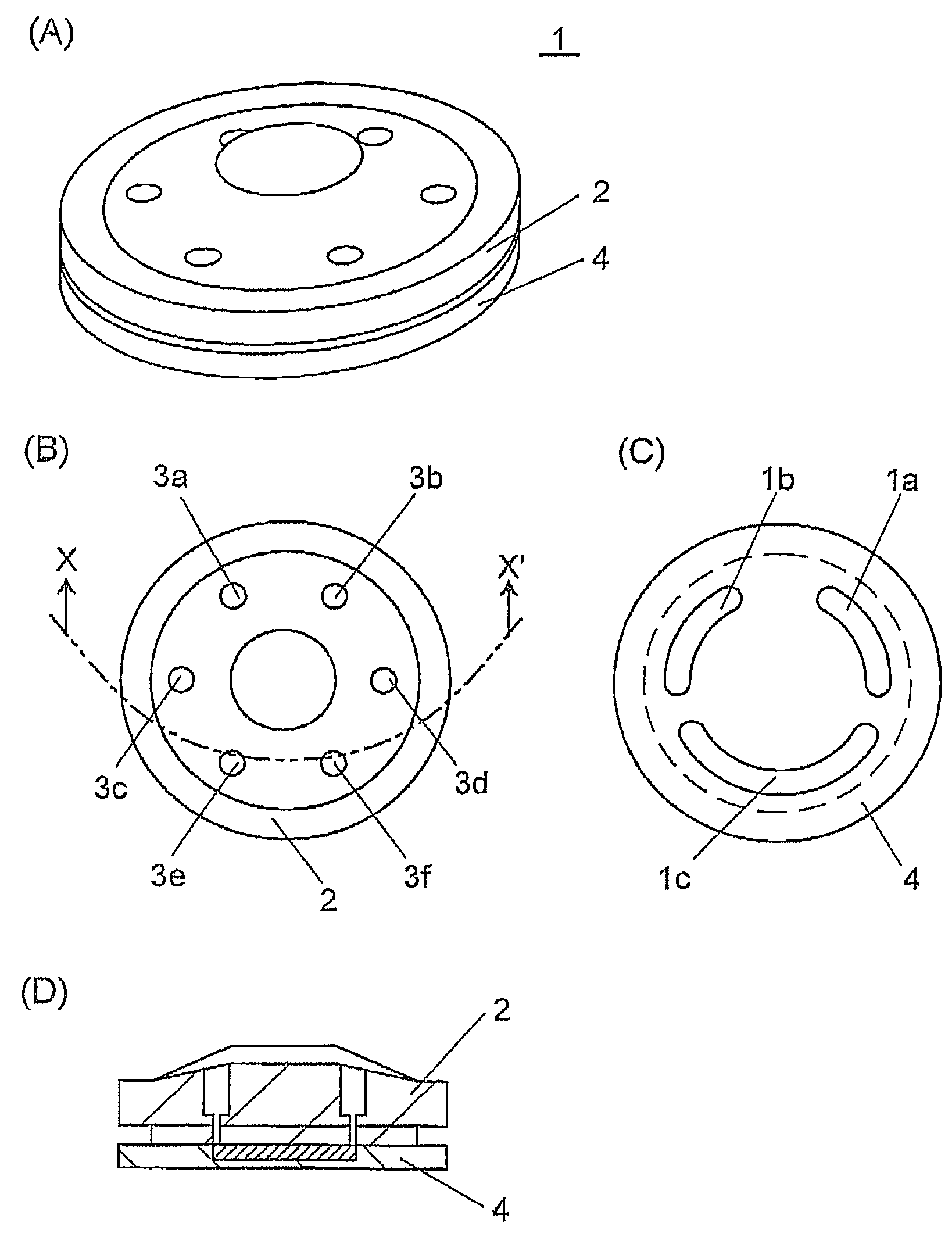
[0039]FIGS. 1A-1D show a flow path switching valve, in which FIG. 1A is a perspective view, FIG. 1B is a plan view of a housing cover, FIG. 1C is a plan view of a rotor, and FIG. 1D is a vertical sectional view of FIG. 1B taken along the line of X-X′. The flow path switching valve 1 is formed by a rotor 4 and a housing cover 2, the rotor 4 is a rotor for switching the flow path, and the housing top 2 also functions as a stator for maintaining liquid-tightness of the rotor 4 during rotating. In this embodiment, in order to reduce the volume in the valve 1, the housing cover 2 can also serve as a stator.

[0040]On the housing cover 2, six ports 3a-3f are disposed for being connected to external flow paths, and the ports 3a and 3b are respectively an IN port and an OUT port facing the trap column, the port 3c is a port for connecting the mobile phase liquid used for condensing, the port 3d is a port fo...


PUM

PropertyMeasurementUnit
central angleaaaaaaaaaa
inner diameteraaaaaaaaaa
flow rateaaaaaaaaaa

Abstract

A flow path switching valve is provided, in which an impact due to the pressure change when a flow path is switched is prevented from being generated. (A) A rotor slot 1c allows an analysis infusion pump 11 to be connected to an analytical column 13, so as to form a flow path (condensing procedure). (B) The rotor of the flow path switching valve 1 is rotated clockwise for 30 degrees, the rotor slot 1c allows the analysis infusion pump 11, the analytical column 13, and a trap column 5 be connected. After the pressure in the trap column 5 is raised to the same pressure level as that of the analytical column 13, the pressure is stabilized, and the pressure difference between the two columns 5 and 13 is counteracted (high-pressure procedure). (C) After the pressure between the two columns 5 and 13 has been stabilized sufficiently, the rotor is further rotated for 30 degrees, and the trap column 5 and the analytical column 13 are connected in series, so the sample analysis can be performed (dissolution procedure and detection procedure).

Description

CROSS-REFERENCE TO RELATED APPLICATION[0001]This application claims the priority benefit of Japanese application serial no. 2006-121389, filed Apr. 26, 2006. All disclosure of the Japanese application is incorporated herein by reference.BACKGROUND OF THE INVENTION[0002]1. Field of the Invention[0003]The present invention relates to a high performance liquid chromatography for separating and analyzing the various compounds in a sample, and an analytical method of the same, and a flow path switching valve used by the same.[0004]2. Description of Related Art[0005]As for mass spectrometers used for determining the structures of proteins or peptides in the field of life science, in order to optimize the sensitivity, it is required to minimize the flow in the high performance liquid chromatograph (HPLC) served as the previous stage of a mass spectrometer.[0006]Generally, the HPLC employed in an ordinary analysis is operated by feeding a liquid as a mobile phase at a flow rate of about 1 m...

Claims


Application Information

Patent Timeline
Patent Type & Authority Patents(United States)
IPC IPC(8): G01N1/00F16K11/074
CPCG01N30/20G01N30/32G01N2030/202Y10T137/86863
Inventor IWATA, YOSUKE
Owner SHIMADZU CORP
Why Eureka
Try Eureka