Fuel cell system, fuel cell system drive method and fuel container for power generation

a fuel cell and power generation technology, applied in the direction of electrochemical generators, cell components, cell component details, etc., can solve the problems of inferior generation efficiency, complicated configuration of fuel cell systems, and lower generation efficiency

Inactive Publication Date: 2009-08-18
CASIO COMPUTER CO LTD
View PDF12 Cites 3 Cited by
  • Summary
  • Abstract
  • Description
  • Claims
  • Application Information

AI Technical Summary

Benefits of technology

[0031]In view of the above-mentioned problem points, the present invention favorably maintains a wet state of the electrolyte membrane of a fuel cell body upon system start-up (upon a power generation operation start-up) and accelerates the electrochemical reaction related to the power generation operation. The object of the present invention is to provide a fuel container for power generation of a fuel cell system which can favorably extract predetermined electrical energy and be practically applied to that fuel cell system.
[0036]Accordingly, since the electrolyte membrane can be rapidly maintained in a predetermined wet state, electricity can be satisfactorily generated. All that is necessary is that the minimum amount of water used for the power generation operation start-up be contained in the fuel container for power generation. Also, because the other contents of the fuel cell container is allocated to contain the fuel for power generation (methanol, etc.), the above-mentioned power generation operation can be continued over a long period of time and extended battery life can be achieved.

Problems solved by technology

However, as for a system which supplies such hydrogen gas directly to a fuel cell, due to the technical aspects of production, storage and supply of hydrogen gas, along with the safety aspect of difficult handling and from an economic viewpoint, practical applications have been attained only in relatively large-sized systems, such as power generation equipment in a business establishment, a vehicle drive power source, etc.
However, in general, as compared with a fuel cell of a fuel reforming supply system, there is a problem that generation efficiency (energy conversion efficiency) is lower.
Also, the configuration of the fuel cell system is complicated.
This is the case even though drastic miniaturization cannot be performed more than a fuel cell system of a fuel direct supply system which can be miniaturized, but has inferior generation efficiency.
Specifically, there is a problem that the electrolyte membrane cannot be adequately maintained in a predetermined wet state as the water produced as a byproduct is recovered upon a power generation operation start-up or immediately after the start-up (upon system start-up).
As a method of solving such a problem, for example, although humidifying the electrolyte membrane in advance to a water vapor hydrated state before shipment of electronic apparatus containing a fuel cell system, etc. has been considered, there are still other related problems.
Notably, after shipment of the electronic apparatus, the electrolyte membrane rapidly dries out due to climate conditions, etc., thus power generation operation becomes impossible.
Also, there is a possibility of an operational malfunction in which the electrolyte layer is destroyed by freezing which produces a defective system.

Method used


Image

  • Fuel cell system, fuel cell system drive method and fuel container for power generation
  • Fuel cell system, fuel cell system drive method and fuel container for power generation
  • Fuel cell system, fuel cell system drive method and fuel container for power generation

Examples


first preferred embodiment

[0047]

[0048]Initially, the entire configuration of the fuel cell system related to the present invention will be explained.

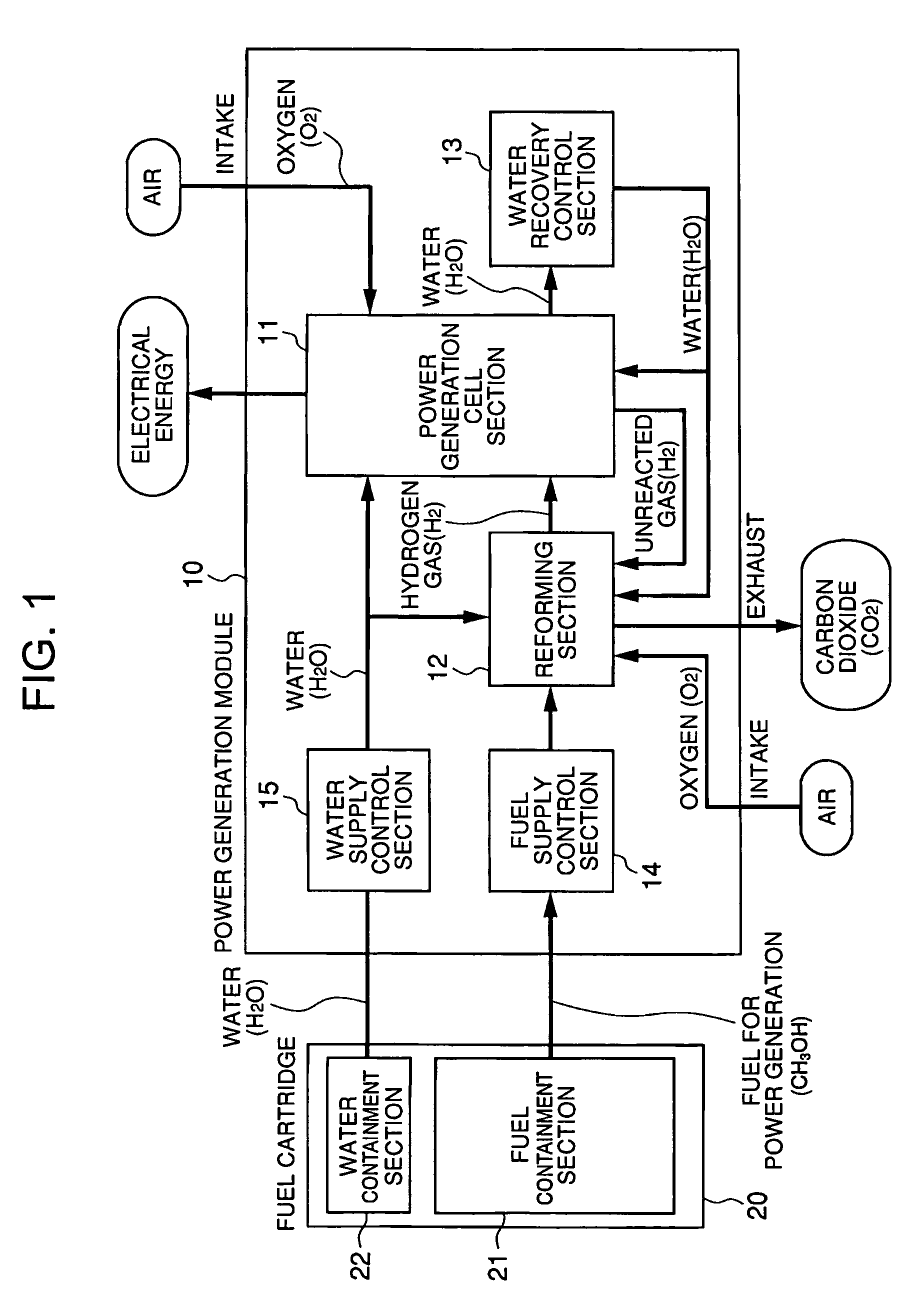
[0049]FIG. 1 a schematic block diagram showing the entire configuration of the first preferred embodiment of the fuel cell system related to the present invention. Here, in regard to a composition equivalent to the fuel cell indicated in the conventional prior art mentioned above, the same or equivalent nomenclature is appended and explanation simplified.

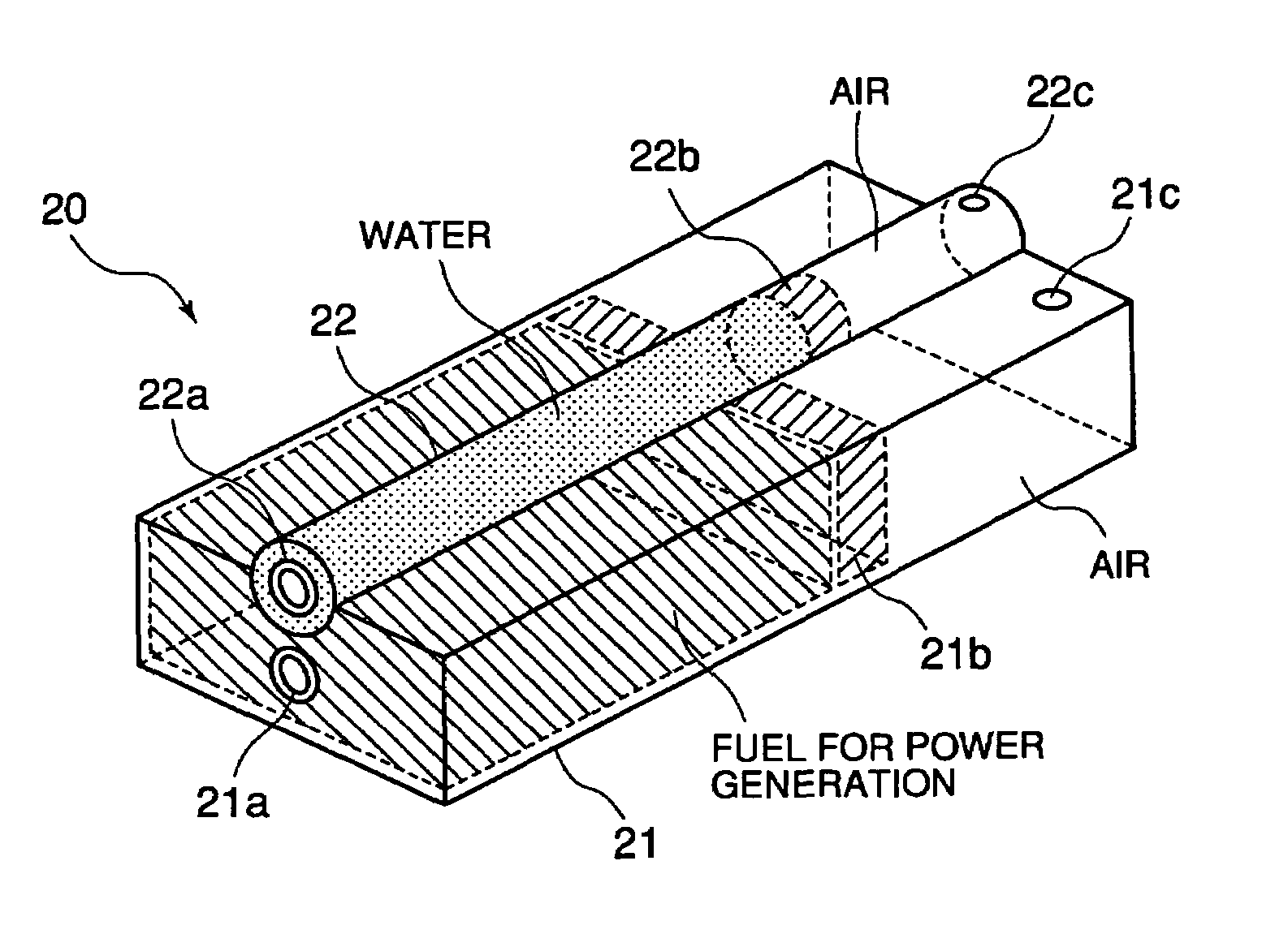
[0050]The fuel cell system related to the present invention as seen in FIG. 1, in summary, has a structure comprising a fuel cartridge 20, a reforming section 12, a power generation cell section 11, a water recovery control section 13, a fuel supply control section 14 and a water supply control section 15. The fuel cartridge 20 (fuel container, fuel container for power generation), individually contains hydrocarbon based fuel for power generation, such as methanol CH3OH, and water H2O. The reforming section 12 (...

second preferred embodiment

[0106]FIG. 5 is a schematic block diagram showing the entire configuration of the second preferred embodiment of the fuel cell system related to the present invention. Here, in regard to a composition equivalent to the first embodiment mentioned above, the same or equivalent nomenclature is appended and explanation simplified.

[0107]Regarding the first preferred embodiment mentioned above, the power generation cell section 11 is explained as a configuration which supplies oxygen O2 (air) used for chemical reaction to the cathode electrode and as a configuration in which the cathode electrode communicates with the ambient air (atmosphere). Also, the fuel cartridge 20 is explained as a configuration which extracts methanol CH3OH and water H2O contained in each containment section 21, 22 from each extraction part 21a, 22a side and supplied to the power generation module 10. Further, the following bodies 21b, 22b are explained as a configuration containing methanol CH3OH and on the other...

third preferred embodiment

[0111]FIG. 6 is a schematic block diagram showing the entire configuration of the third preferred embodiment of the fuel cell system related to the present invention. Here, in regard to a composition equivalent to the first or second embodiments mentioned above, the same or equivalent nomenclature is appended and explanation simplified.

[0112]The fuel cell system related to the preferred third embodiment as seen in FIG. 6, with the structure (refer to FIG. 5) shown in the second preferred embodiment mentioned above, is provided with the switching valves VL1˜VL7 (path opening and closing parts), at least, in all of the paths (feed routes) which supply the hydrogen gas H2, water H2O and oxygen O2 to the power generation cell section 11; or in the main paths and the path (discharge route) which discharge the byproduct produced in the power generation cell section 11 or the reforming section 12. Upon start-up of the fuel cell system (power generation operation start-up), each of the swit...


PUM

PropertyMeasurementUnit
temperatureaaaaaaaaaa

Abstract

A fuel cell system having a fuel cell which performs a power generation operation with fuel for power generation of a fuel container; a water supply control section which extracts water from the fuel container and supplies the water to the fuel cell before the fuel cell performs the power generation operation. A wet state of an electrolyte membrane in the fuel cell body is adequately maintained during system start-up (upon commencement of a power generation operation) and an electrochemical reaction related to the power generation operation is accelerated. In this manner, the fuel cell system which can adequately extract predetermined electrical energy and a fuel container for power generation applicable to that fuel cell system are provided.

Description

CROSS-REFERENCE TO RELATED APPLICATION[0001]This application is based upon and claims the benefit of priority from the prior Japanese Patent Application No. 2004-263318, filed Sep. 10, 2004, the entire contents of which is incorporated herein by reference.BACKGROUND OF THE INVENTION[0002]1. Field of the Invention[0003]The present invention relates to a fuel cell system, a fuel cell system drive method and a fuel container for power generation. More particularly, the present invention relates to a fuel reforming supply type fuel cell system which performs power generation using hydrogen gas produced from fuel for power generation and favorably applied to this fuel cell system. In addition, the present invention relates to a fuel container for power generation having a detachable structure relative to the fuel cell main body which comprises a power generation module.[0004]2. Description of the Related Art[0005]In recent years there has been increasing public interest in environmental ...

Claims


Application Information

Patent Timeline
Patent Type & Authority Patents(United States)
IPC IPC(8): H01M8/00H01M2/00H01M8/10
CPCH01M8/04126H01M8/04156H01M8/04223H01M8/04208Y02E60/50H01M8/04225H01M8/04228H01M8/04302H01M8/04303H01M8/241H01M8/2457
Inventor KABASAWA, YASUNARI
Owner CASIO COMPUTER CO LTD
Why Eureka
Try Eureka