Shake correcting mechanism and camera having same shake correcting mechanism

a technology of shake correction mechanism and camera, which is applied in the field of shake correction mechanism, can solve the problems of unavoidable increase in thickness and reduction of camera size, and achieve the effect of improving the long-term reliability of the camera and avoiding damage to the flexible wiring member

Inactive Publication Date: 2009-08-18
KONICA MINOLTA PHOTO IMAGING
View PDF7 Cites 24 Cited by
  • Summary
  • Abstract
  • Description
  • Claims
  • Application Information

AI Technical Summary

Benefits of technology

[0011]According to this configuration, even when the image pickup device is swung in two distinct axis directions by the driving section, the flexible wiring member can follow the motion and deform freely on the basis of the degree of margin provided by the bending in the space part. Thus, even when the deforming forces in the two distinct axis directions act on the flexible wiring member, a problem such as disconnection does not arise, while the flexible wiring member does not block the swing operation of the image pickup device performed by the shake correction unit. Thus, in the camera with shake correction function in which a shake correction unit and a control board are arranged at adjacent positions to each other in a direction of almost the same plane so that the thickness size is reduced in the optical axis direction, the flexible wiring member for electrically connecting the two elements can be wired in an optimal manner.
[0013]According to this configuration, even in the case of the flexible wiring board having a belt shape where the deformation direction is restrictive, the swing of the image pickup device can be followed so that bending deformation and twist deformation can be performed freely. This provides a camera of such a configuration that the advantage of the compactness of the belt-shaped flexible wiring board is utilized while the swing of the image pickup device is treated appropriately.
[0015]According to this configuration, since the planar space is prepared in alignment with the side wall part of the rectangular-tube shaped frame, a space where the flexible wiring member is to be bent is easily ensured. In particular, when the flexible wiring board having a belt shape is used, the space where the bending deformation and twist deformation are performed is efficiently ensured. Thus, the flexible wiring member can be accommodated in the space part with an improved deformation follow-up property.
[0017]This configuration avoids damage in the flexible wiring member which could be caused by the shake correction of the image pickup device, and hence improves the long term reliability of the camera with shake correction mechanism.

Problems solved by technology

Nevertheless, as in the camera with shake correction mechanism of Patent Document 1, when the shake correction unit and the control board are built into the camera body case in a manner stacked in the optical axis direction, the thickness size increases unavoidably in the optical axis direction of the camera, and hence prevents the size reduction of the camera.

Method used


Image

  • Shake correcting mechanism and camera having same shake correcting mechanism
  • Shake correcting mechanism and camera having same shake correcting mechanism
  • Shake correcting mechanism and camera having same shake correcting mechanism

Examples


Embodiment Construction

[0045]Embodiments of the invention are described below with reference to the drawings.

[0046]First, the invention is outlined below with reference to FIGS. 1-3.

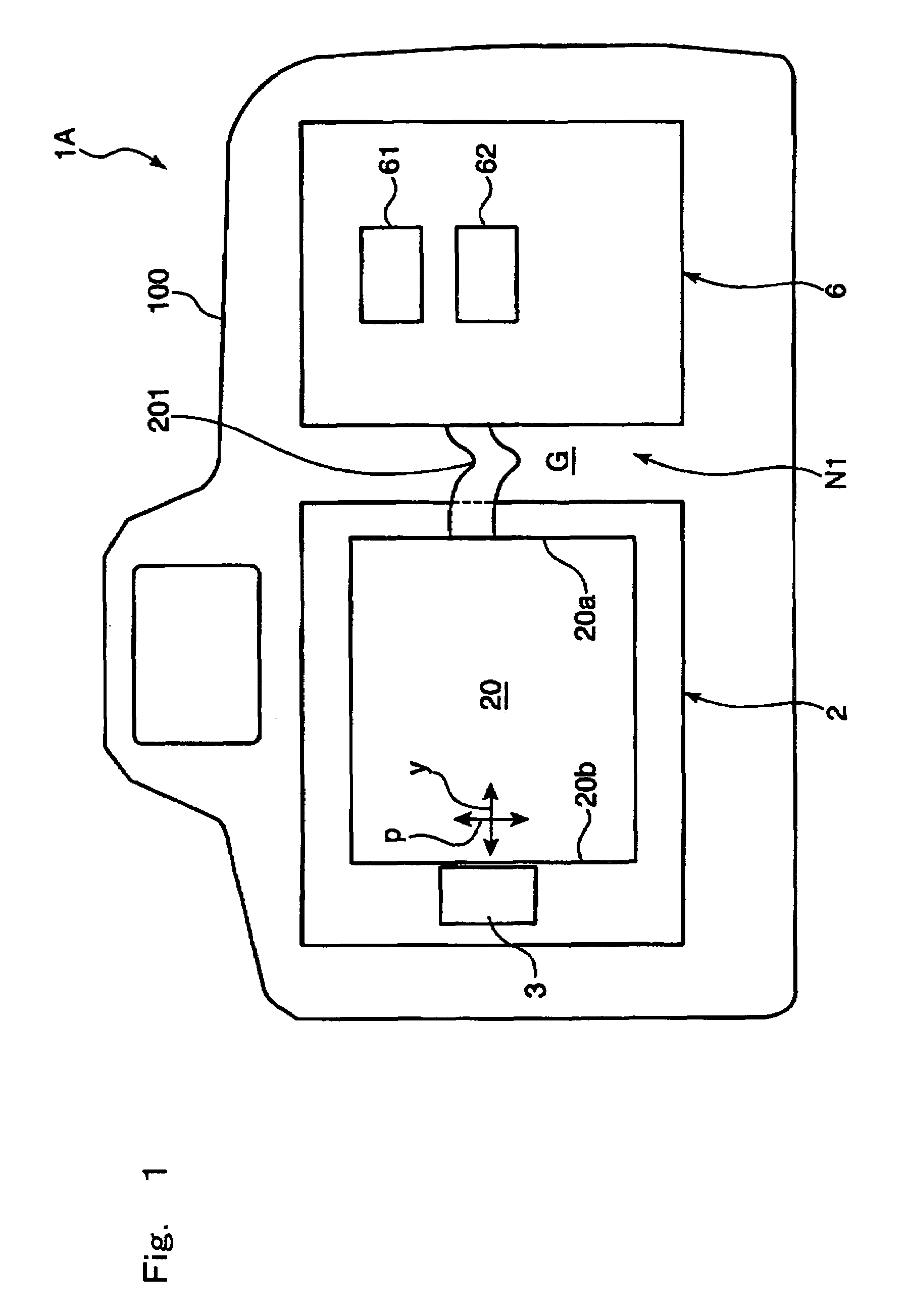
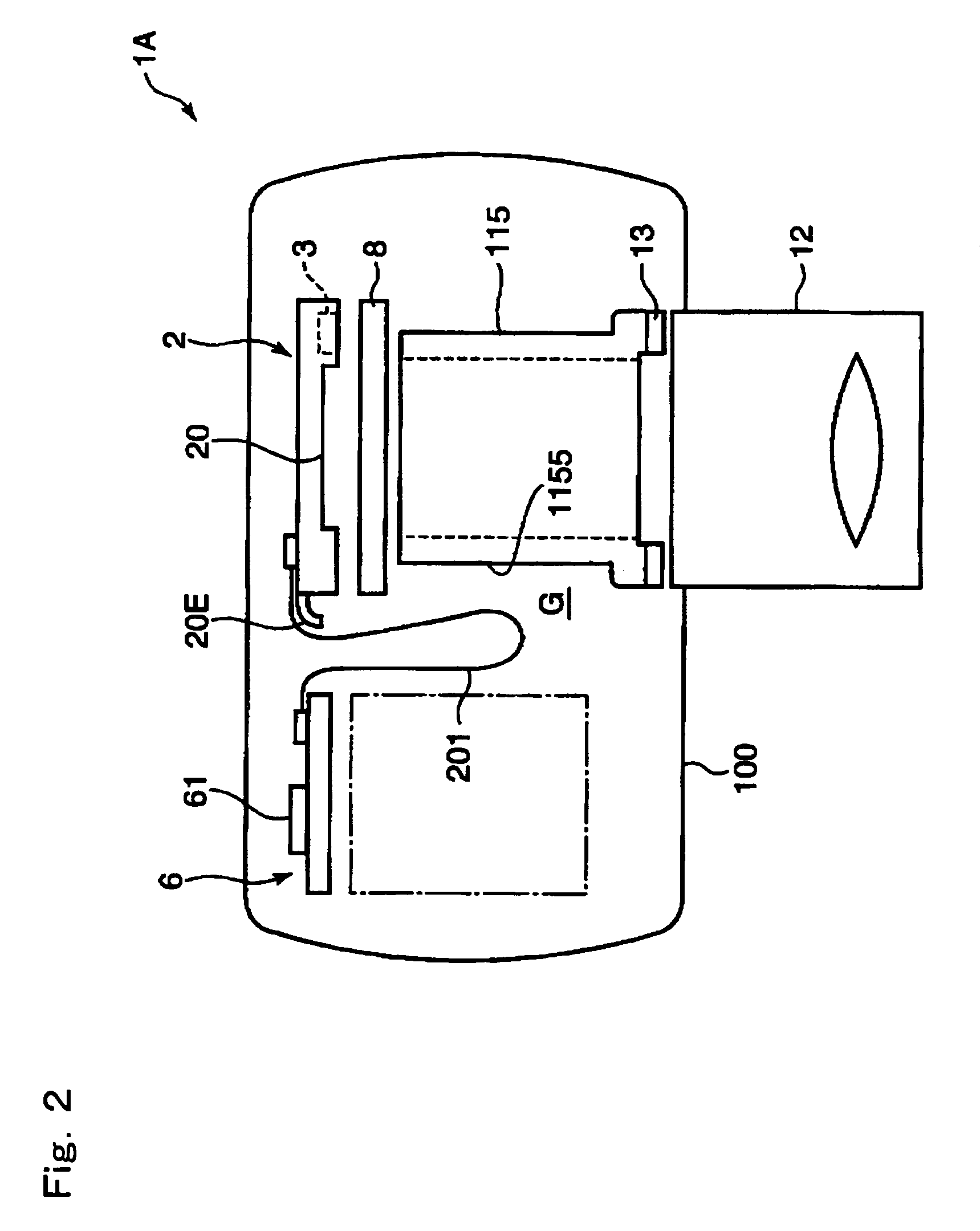
[0047]FIGS. 1 and 2 are built-in arrangement diagrams schematically showing the configuration of the invention. FIG. 1 is a rear view, while FIG. 2 is a top view. In this camera with shake correction mechanism 1A, a shake correction unit 2 retaining an image pickup device 20 in a swingable manner and a control board 6 provided with electronic components such as an ASIC 61 and a drive control circuit 62 are arranged inside a body casing 100 at adjacent positions to each other in a direction of almost the same plane. The phrase “arranged at adjacent positions to each other in a direction of almost the same plane” indicates that the two elements are arranged close to each other in a transverse direction (direction perpendicular to the camera optical axis) without overlapping in the optical axis direction. Thus, as long as the sha...


PUM


Abstract

A camera with shake correction mechanism according to the invention comprises: an image pickup device for picking up object light; shake detecting device for detecting a shake exerted to a camera body; a shake correction unit provided with a driving section for exerting a swing force for swinging the image pickup device in a direction perpendicular to the optical axis; a control board on which electronic components are mounted; and a flexible wiring member for electrically connecting the shake correction unit to the control board, wherein the shake correction unit and the control board are arranged at adjacent positions to each other in a direction of almost the same plane, while in an adjacent part of the two elements, a space part is set up that can accommodate the flexible wiring member in a bent state. According to this configuration, in the camera in which a shake correction unit and a control board are arranged at adjacent positions to each other in a direction of almost the same plane so that the thickness size is reduced in the optical axis direction, the flexible wiring member for electrically connecting the two elements can be wired in an optimal manner.

Description

[0001]This application is based on Japanese Patent Application No. 2004-264408 filed in Japan on 10 Sep. 2004, the entire content of which is hereby incorporated by reference.FIELD OF THE INVENTION[0002]The present invention relates to a shake correction mechanism for correcting a camera shake or the like and to a camera with shake correction mechanism such as a digital still camera and a digital video camera provided with a shake correction mechanism.DESCRIPTION OF RELATED ART[0003]As an example of an active type shake correction mechanism for swinging all or part of an optical system and thereby correcting deviation of the photographing optical axis caused by a camera shake or the like, JP-A No. 2003-110929 (Patent Document 1, hereafter) discloses a shake correction mechanism of the type that the image pickup device is swung. This shake correction mechanism of image pickup device swing type avoids the necessity of a lens dedicated for shake correction. Thus, even a small mechanism...

Claims


Application Information

Patent Timeline
Patent Type & Authority Patents(United States)
IPC IPC(8): H04N5/228
CPCG03B5/00G03B19/12H04N5/2253H04N5/23287H04N5/23248G03B2217/002G03B2205/0038H05K1/0393G03B2205/0061H04N23/54H04N23/68H04N23/687
Inventor HIROTA, TOSHIHIKOSUGITA, MITSUHIROTANAKA, YOSHIHARU
Owner KONICA MINOLTA PHOTO IMAGING
Why Eureka
Try Eureka