Disc frame vibration dampening system

a vibration dampening system and disc frame technology, applied in the field of agricultural implements, can solve the problems of limited effectiveness in reducing the impact of various obstructions on the disc frame mainframe, and the disc harrow may encounter various obstructions, so as to reduce the amount of force that is transferred to the mainframe and limit the impact of ground variations.

Inactive Publication Date: 2009-08-25
BLUE LEAF I P INC
View PDF28 Cites 20 Cited by
  • Summary
  • Abstract
  • Description
  • Claims
  • Application Information

AI Technical Summary

Benefits of technology

[0007]The present invention is directed to a disc harrow having a disc frame carrying one or more disc gangs and coupled to a mainframe. The disc frame is designed to allow the disc gangs to respond to variations in the farmland terrain to limit the impact of ground variations when encountered during the harrowing process. Specifically, the disc frame is coupled to the mainframe by a series of struts that hold the disc frame at a relatively constant height yet absorb the impact that results when the disc gangs encounter ground variation. Each strut includes a spring component that is biased to maintain a constant depth of the disc gangs. Each strut also has a damper component that absorbs the movement associated with the disc gang as it follows the ground contours and variations. As a result, the force of the impact is absorbed by the strut and the amount of force that is transferred to the mainframe is reduced.
[0010]In accordance with another aspect of the present invention, an apparatus for tilling crop residue and soil is presented. The apparatus has a disc harrow including a first disc gang and a second disc gang connected to the first disc gang by a floating frame. A mainframe is defined by a pair of rails and a plurality of transverse supports, and carries the disc harrow and is coupled to the floating frame by at least one strut. The at least one strut is adapted to maintain the disc harrow at a defined depth during normal working operation and automatically dampening any force presented when the disc harrow encounters ground variation during harrowing of a field.

Problems solved by technology

During harrowing of the farmland the disc harrow may encounter various obstructions, such as rocks, stumps, and roots.
While such cushions are generally effective at maintaining a uniform depth of the disc gangs and flexing in response to any obstruction, their effectiveness is limited at reducing the impact of the obstruction on the harrow mainframe.

Method used


Image

  • Disc frame vibration dampening system
  • Disc frame vibration dampening system
  • Disc frame vibration dampening system

Examples


Embodiment Construction

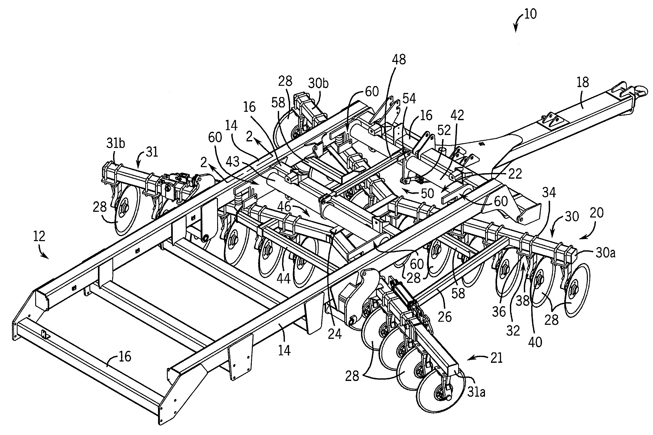
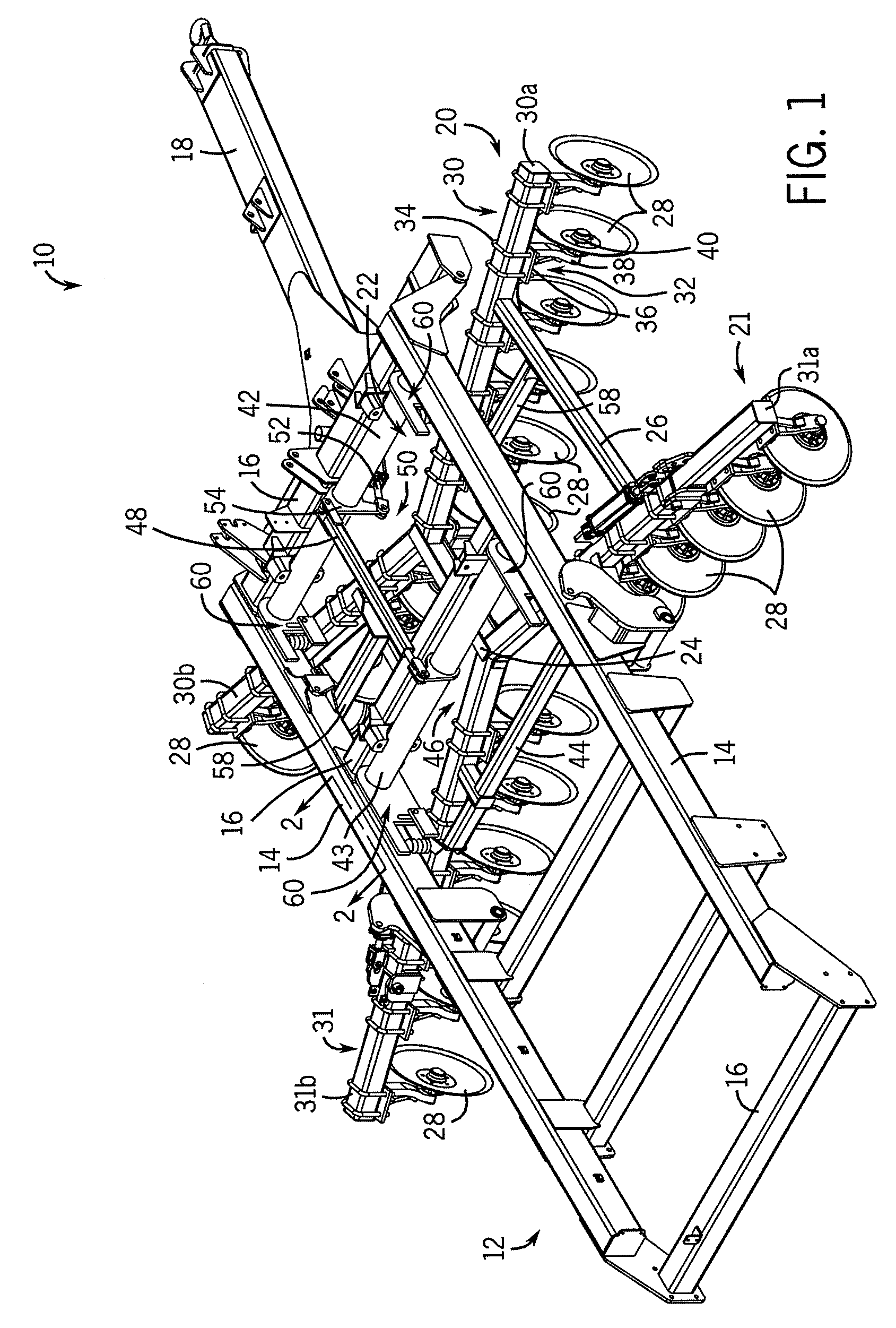
[0017]Referring now to FIG. 1, a disc harrow 10 has a mainframe 12 defined by a pair of rails 14 connected to one another by a series of transverse supports 16 spaced from one another along the length of the rails 14. The disc harrow 10 is designed to be towed by a tractor or other powered device. In this regard, the disc harrow 10 includes a hitch 18 for connecting the mainframe 12 to the tractor. In the illustrated embodiment, the disc harrow 10 includes a pair of disc gangs 20, 21 mounted to the mainframe 12 using a subframe or disc frame 22, which will be described in greater detail below. The pair of disc gangs includes a forward disc gang, designated by numeral 20, and a rearward disc gang, designated by numeral 21.

[0018]The disc gangs 20, 21 are connected to one another by an I-beam 24 and a pair of gang braces 26, only one of which is visible in the figure. Each disc gang 20, 21 has a series of reels or discs 28 each of which is mounted to a disc support beam 30, 31, respect...


PUM


Abstract

A disc harrow composed of one or more disc gangs has a subframe coupled to the disc gangs to move the disc gangs in response to variations in farmland terrain to limit the impact of ground variation when encountered during the harrowing process. When the obstruction is cleared, the subframe automatically returns the disc gangs to their pre-obstruction position. In addition to reducing the potentially-damaging impact of obstructions, the subframe also maintains a more consistent reel depth during undulations or changes in the farmland terrain, such as during harrowing of slopes or unleveled fields such as valleys, near waterways, and along fence rows.

Description

FIELD OF THE INVENTION[0001]The present invention relates generally to agricultural implements, and in particular, to an implement having a spring and damper assembly to which a disc gang is mounted that maintains the disc gang at a relatively constant height yet absorbs the impact imparted by the disc gang when the disc gang encounters variations in terrain contours.BACKGROUND OF THE INVENTION[0002]Once a crop has been harvested, residual crop materials frequently remain on the farmland surface. Typically, these residual crop materials are incorporated within the soil profile of the farmland in an effort to maintain soil nutrient integrity. For example, management of corn cropped fields commonly includes the incorporation of the residual corn stalks with field soil once the corn, and occasionally a portion of the stalk, has been harvested. Whereas some growers harvest a majority of the kernel, cob, and stalk material, others harvest only the kernel and discharge a majority of the c...

Claims


Application Information

Patent Timeline
Patent Type & Authority Patents(United States)
IPC IPC(8): A01B35/28
CPCA01B61/04A01B21/083
Inventor NEWMAN, MICHAEL R.
Owner BLUE LEAF I P INC
Why Eureka
Try Eureka