Magnetic head tester using magnetic disk with pre-written servo

a technology of servo data and magnetic disk, which is applied in the direction of magnetic recording, instruments, data recording, etc., can solve the problems of discrepancy between tracks, high cost and time consumption, and add to the expense of the tester, so as to achieve more accurate, reproducible and efficient process, and more accurate and efficient process

Active Publication Date: 2009-08-25
HEADWAY TECH INC
View PDF10 Cites 3 Cited by
  • Summary
  • Abstract
  • Description
  • Claims
  • Application Information

AI Technical Summary

Benefits of technology

[0023]It is a first object of this invention to make the writing of servo track data on disks used for testing read / write heads a more accurate, reproducible and efficient process and, thereby, to make the head testing process itself a more accurate, reproducible and efficient process.
[0025]It is a third object of this invention to provide a method of eliminating the continual servomechanism corrections of repeatable runout (RRO) associated with a rotating disk mounted within a host head testing device when said disk has had its servo data written in a different device.
[0026]It is a fourth object of the present invention to improve servo accuracy in a head testing device by minimizing track following error associated with attempts by the head to follow an eccentric path.
[0027]It is a fifth object of the present invention to eliminate problems with mechanical hysteresis and resonance that occur when an actuator-mounted head requires rapid movements to follow track eccentricities that include the effects of repeatable runout.
[0028]It is a sixth object of the present invention to provide a less costly head testing device by eliminating the need for servo-writing components such as micro-positioners within the device itself.
[0029]The objects of the present invention are achieved by introducing a disk or a plurality of disks, each pre-written with servo data, into a head testing device and thereby eliminating the need for a servo data writing apparatus within the tester itself. The servo data is written onto the disk (or disks) using a dedicated servo writing apparatus, which, thereby, improves the quality of the servo tracks and, therefore, the accuracy, repeatability and efficiency of the head testing process. As a result, the servo-writing elements contained within the dedicated writer will no longer need to be made a part of the head tester, thereby significantly reducing the cost of the head tester as well as reducing the time required to complete the head testing process. The repeatable runout (RRO) associated with the use of pre-written disks is then effectively removed from the position error signal (PES) generated by the servomechanism within the tester, so that the RRO is effectively ignored and the actuator-mounted head does not follow an eccentric path. The RRO is made ignorable by the tester servomechanism by simply obtaining an excellent approximation to the RRO by averaging the runout values of selected servo track sectors (the differences between a fixed head location and a servo track location) while the actuator is operated at a low servo bandwidth. The average so obtained, which is an excellent approximation to the track runout, is then subtracted from the PES of the servomechanism while the servomechanism is operated at full bandwidth.

Problems solved by technology

Random vibrations can easily move the head slightly from its target, but much of the position error is related to the fact that the typical magnetic disk is slightly warped or generally fails to rotate perfectly on its spindle.
Therefore, when the disk rotates improperly, there is a discrepancy between the track followed by the actuator (and mounted head) and a circular track produced by the servo data writing process.
Writing accurate servo data on the disk is an important, expensive and time consuming task that is done within the head tester itself using an open-loop or closed-loop micro-positioner and the tester's head.
The additional elements within the tester needed to write servo data, including the micro-positioner and its associated circuitry, add greatly to the expense of the tester.
In addition, the use of these additional elements, as noted, adds to the time required to complete the testing process.
Even with the added time and expense, however, the repeatability of the servo pattern on a plurality of disks is often questionable and it is difficult to verify pattern accuracy.
This is because the head testing device is not an optimal device within which to write servo data.
A problem arises if the temporary information is of insufficient accuracy to permit the disk to be mounted for writing of the permanent information.
A problem arises, however, when a disk that has its servo tracks written in one apparatus is then transferred to another.
The problem is a result of the fact that servo data is written on circular tracks that are substantially concentric when originally written on the disk, but these tracks will generally be eccentric when the disk is rotated by the drive spindle of the apparatus to which it is transferred (the host apparatus).
This, of course, will be the inevitable result if the drive spindle of the original servo writer has even the slightest wobble or if the disk itself slips, is warped or off-center, or if the writing apparatus was subjected to thermal or mechanical shocks during the writing process or if the host apparatus has similar problems.
It is to be noted that the RRO problem is not restricted to head testing devices, but is also a common problem in the disk drives of actual DASD's themselves.
Wherever it occurs, accurate positioning of the read / write head becomes nearly impossible without additional information being present to guide the head to the correct track positions and, when possible, to correct for RRO in some systematic way.
Along with the repeatable runout that is associated with off-center drive spindles or warped disks, there is the more difficult problem of non-repeatable runout, NRRO, associated with random mechanical, electrical and thermal perturbations of the drive system and / or disk.

Method used


Image

  • Magnetic head tester using magnetic disk with pre-written servo
  • Magnetic head tester using magnetic disk with pre-written servo
  • Magnetic head tester using magnetic disk with pre-written servo

Examples


Embodiment Construction

[0034]The present invention teaches a method of operating a magnetic read / write head testing apparatus (commonly referred to as a “spin stand”) using disks on which servo track information has been externally pre-written in a dedicated servo track writer. The head testing apparatus, therefore, lacks the servo-writing mechanisms that are now a part of the dedicated servo-writer.

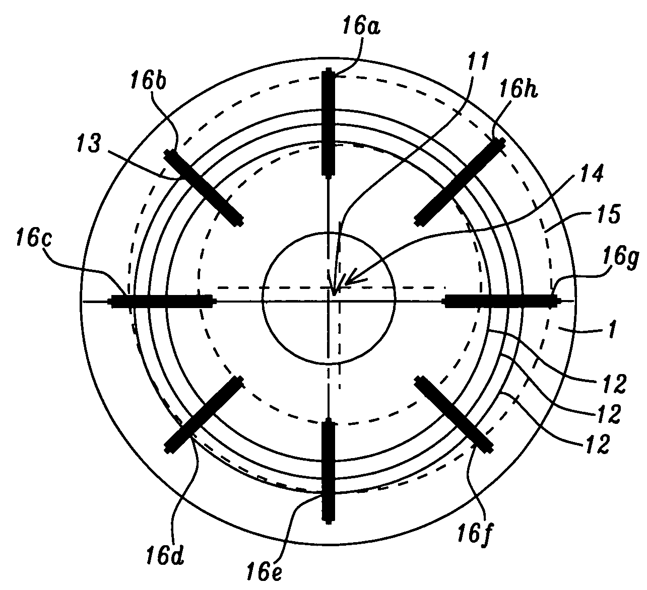
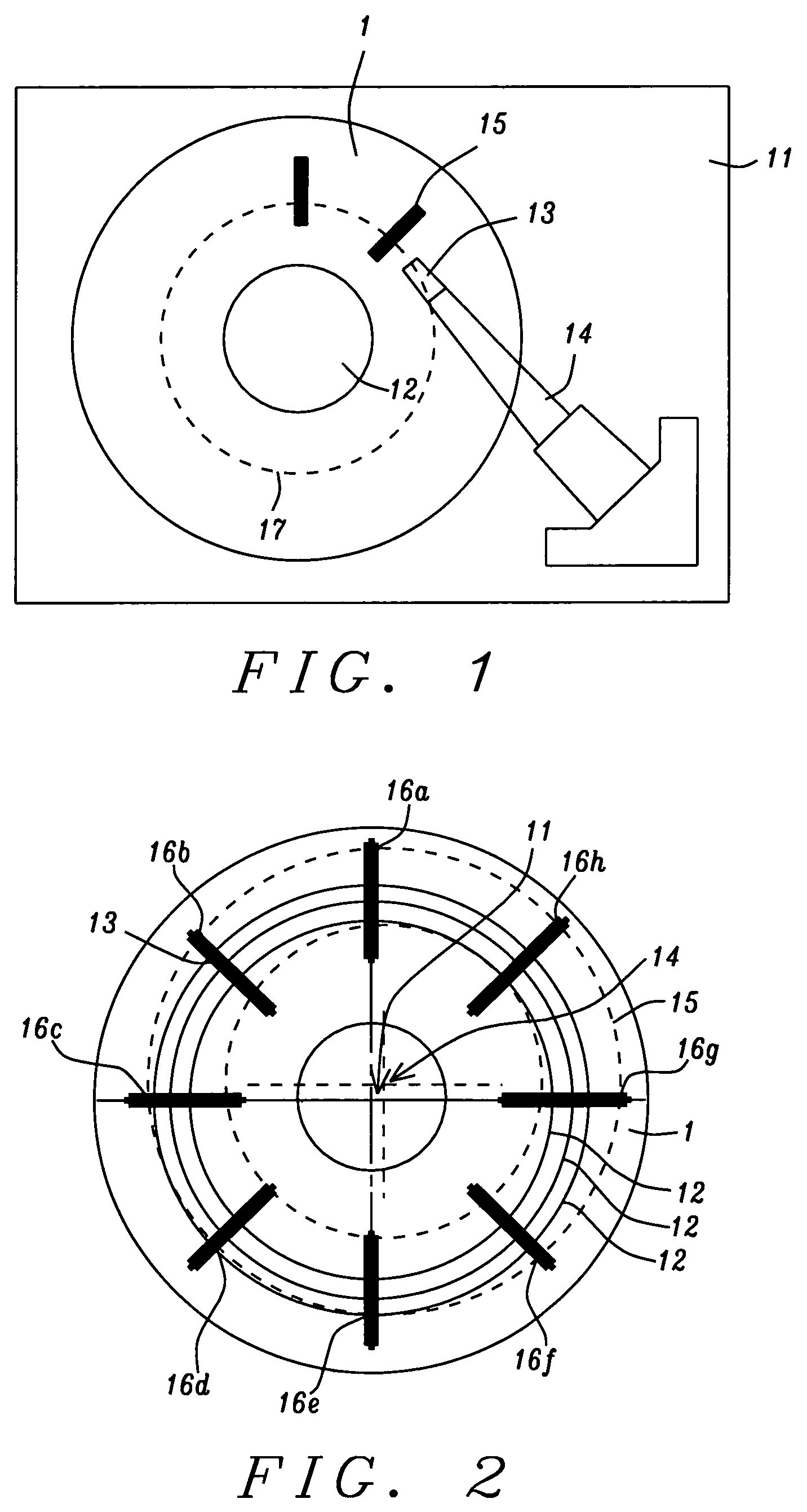
[0035]Referring first to FIG. 1, there is shown a schematic illustration of a head testing apparatus (spin stand) that does not include a servo track writing apparatus such as a micro-positioner. In accord with the present invention, such servo track writing apparatus is not required in the head tester because the magnetic disk to be mounted therein is already pre-written with the necessary servo information through the use of an external servo track writing apparatus (not shown). FIG. 1 schematically shows such a typical head testing apparatus. The apparatus, sometimes called a “spin stand,” includes a base (...


PUM

PropertyMeasurementUnit
riaaaaaaaaaa
magnetic head testingaaaaaaaaaa
angular widthaaaaaaaaaa

Abstract

A method for operating a head testing apparatus (spin stand) using a mounted hard disk that has had its servo track information pre-written in an external servo-writing apparatus rather than in the testing apparatus itself. This insures more accurate servo-track writing and renders the testing operation more efficient. The problem of repeatable runout (RRO) associated with the transfer of a disk written in one machine to another is eliminated by forming a corrected position error signal (PES) by subtracting the average offset of one or more servo sector locations previously calculated using limited bandwidth operation of the servomechanism, from the position error signal generated during full bandwidth servo operation of the apparatus.

Description

BACKGROUND OF THE INVENTION[0001]1. Field of the Invention[0002]This invention relates generally to a device for testing magnetic read / write heads and more specifically to such a device in which there is a rotating magnetic disk on which servo information has been written.[0003]2. Description of the Related Art[0004]Before their installation in a conventional direct access storage device (DASD), magnetic read / write heads are first tested in a device specifically designed for the testing process. A magnetic head tester is basically a rudimentary disk drive that includes a drive motor and spindle (called a spin stand), at least one magnetic disk mounted on the drive motor spindle and capable of being rotated thereby, an actuator on which the head to be tested is mounted and an electro-mechanical system, called a servomechanism (or, equivalently, a servo-control mechanism), for accurately positioning the actuator (and its mounted head) relative to the rotating disk. The testing device ...

Claims


Application Information

Patent Timeline
Patent Type & Authority Patents(United States)
IPC IPC(8): G11B5/596
CPCG11B5/59627G11B5/455
Inventor SHRINKLE, LOUHU, DAVIDCRILL, PETERYEE, MATTHEW
Owner HEADWAY TECH INC
Why Eureka
Try Eureka