Bulkhead connector

a technology of connectors and bulkheads, applied in the direction of couplings, cable installations in underground tubes, coupling devices, etc., can solve the problems of preventing cross-contamination between isolated and external environments, preventing leakage, and preventing the possibility of leaking

Active Publication Date: 2009-09-01
GL TOOL & MFG
View PDF12 Cites 59 Cited by
  • Summary
  • Abstract
  • Description
  • Claims
  • Application Information

AI Technical Summary

Benefits of technology

[0048]In this arrangement the first and the second gaskets are sized and shaped so is to be received in the gap and the gaskets are deformable under compression so as to seal against the first side of the first wall about the bore formed therein and against the third surface of the second wall about the bore formed therein and to cause the first top surface of the first gasket and the first bottom surface of the second gasket to collapse against a conduit passing between the gaskets to form a leak-proof seal around the exterior of the conduit. Ideally, the cover mea...

Problems solved by technology

In each case, it is necessary to ensure that the passage of the wire through the bulkhead connector does not provide any means by which cross-contamination between the isolated and external environments may occur.
The disadvantage of using curable sealants is that the gaps between the bores and the conductors may not be filled uniformly and therefore leakage may still occur.
Another disadvantage lies in the difficulty of disassembling the wires once the sealant has cured and the run has been completed.
Furthermore forming curable seals is an expensive and time consuming process.
The above mentioned disadvantages associated wi...

Method used


Image

  • Bulkhead connector
  • Bulkhead connector
  • Bulkhead connector

Examples


Embodiment Construction

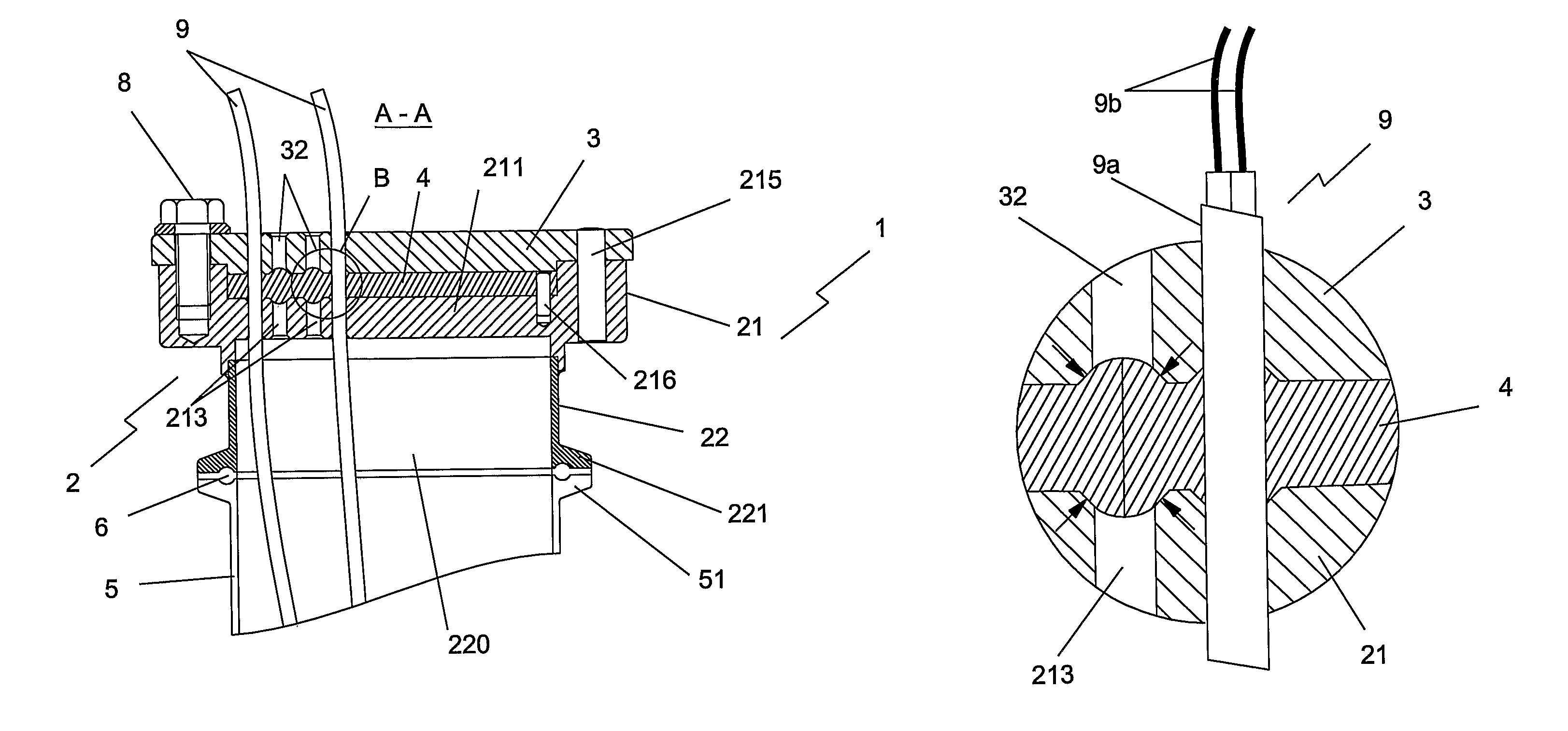
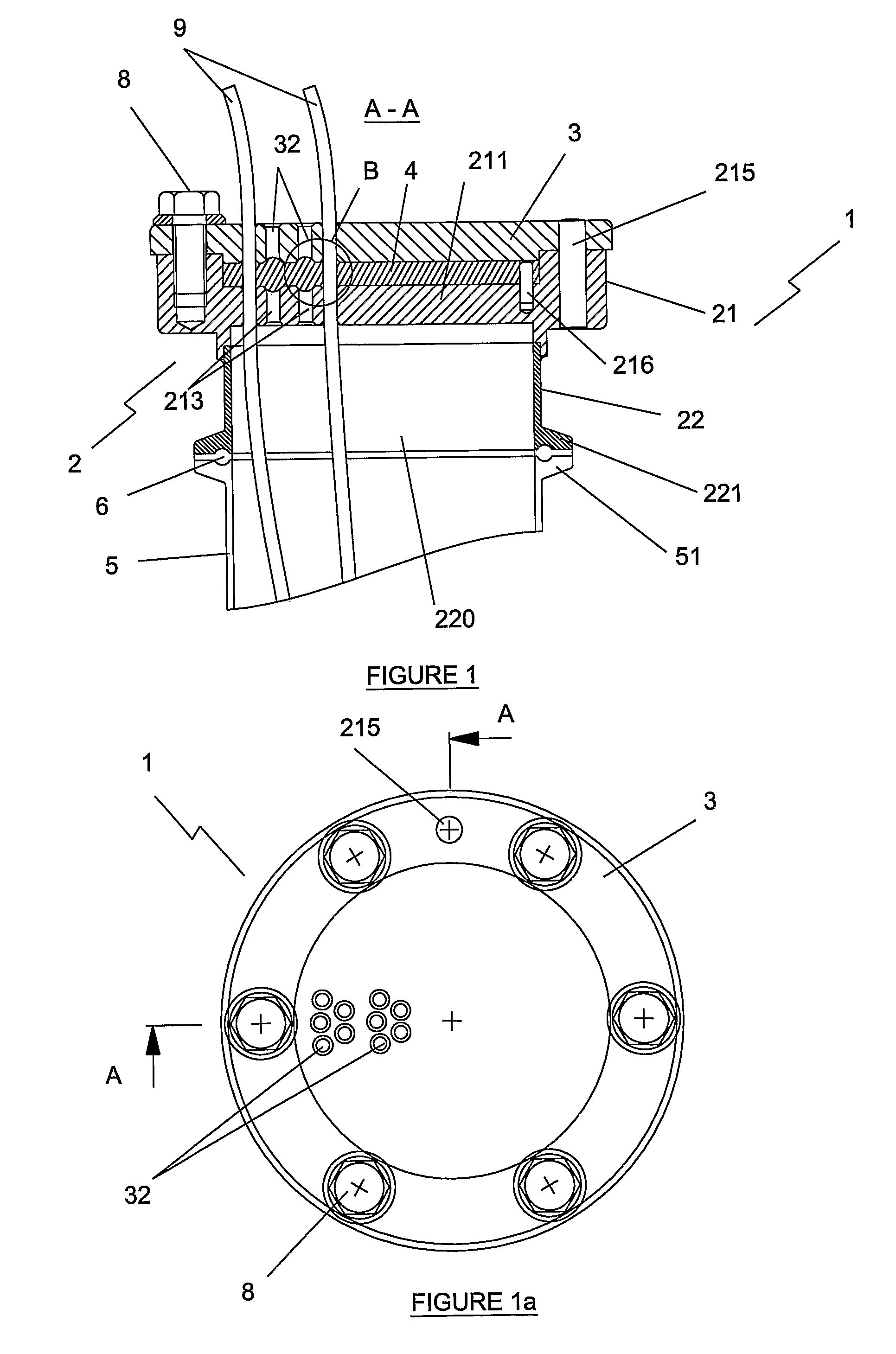
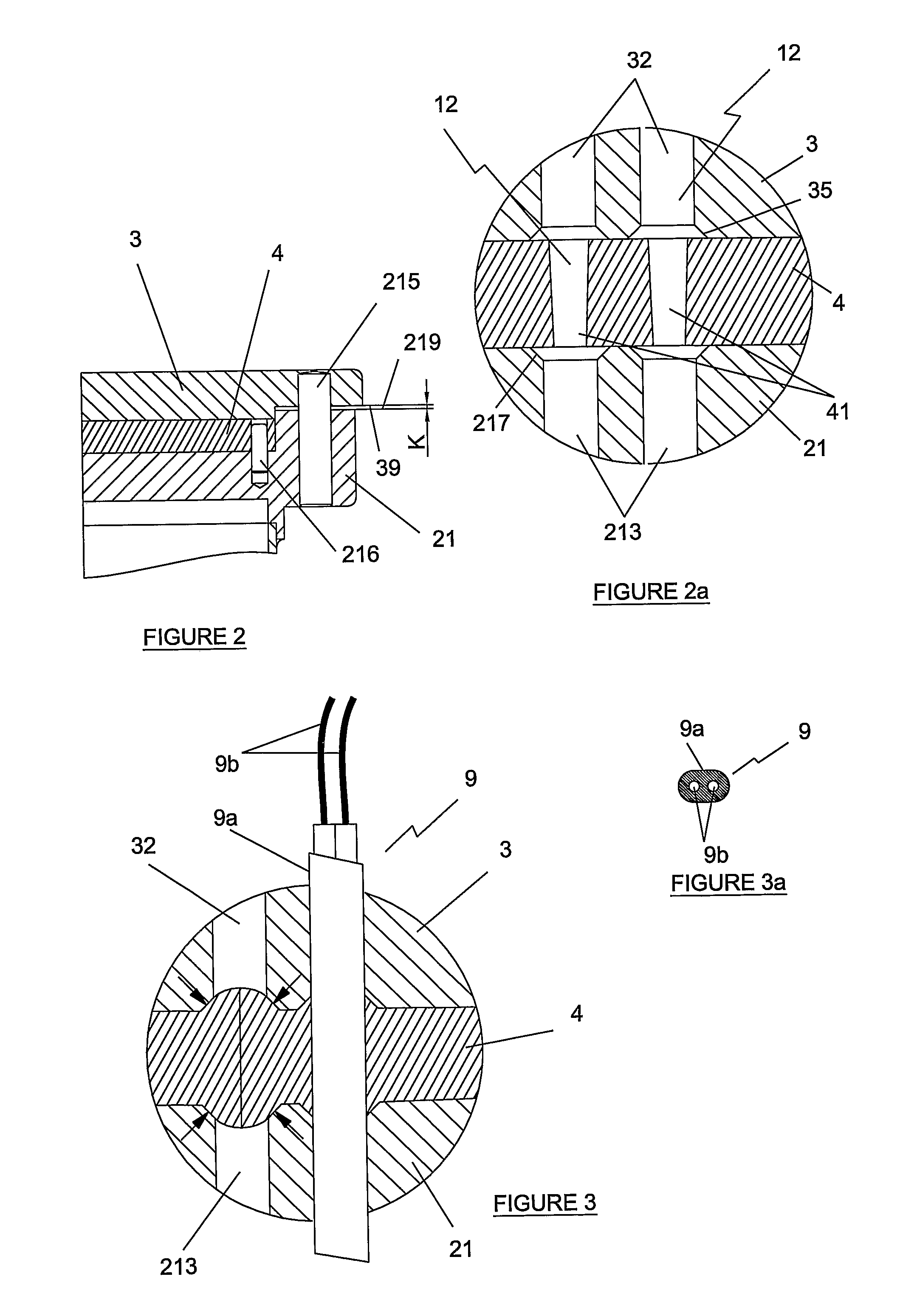
[0091]A most preferred embodiment of the bulkhead connector according to the invention will now be described with reference to FIGS. 1 to 16 and is indicated generally by reference numeral 1. The bulkhead connector 1 will be described by example in an application to a lyophilizing apparatus and more specifically to sealingly feeding insulated electrical conductors 9 of thermocouples through the bulkhead connector 1 from an environment with an atmospheric pressure into a vacuum chamber of the lyophilizer. It is to be understood that the application is not in any way limited to use in such an apparatus and in fact has application in any apparatus in which lines, conductors, piping or other conduits are to be lead, for any suitable reason, between two different areas or atmospheres which must be mutually Isolated.

[0092]Referring to FIGS. 1 to 16, the first embodiment of the bulkhead connector 1 comprises a tubular housing 2, a lid 3 securable to the housing and a resiliently deformable...


PUM


Abstract

The present invention relates to a bulkhead connector assembly providing a sealing arrangement for sealingly feeding a conduit between two environments. The assembly provides a first and second coupling components having a first and second surface respectively. A gap is formed between the first and second surfaces. The first coupling component has an aperture which extends between the first surface and a first environment and the second coupling component has an aperture which extends between the second surface and a second environment. Each aperture is adapted for receiving a conduit therethrough. A resiliently deformable gasket is provided to be placed into the gap and the gasket also is provided with a bore for a conduit to pass through the gasket. Means for compressing the gasket in the gap are provided to deform the gasket on compression so as to collapse the gasket bore against itself or against any conduit occupying the bore, so as to form a leak-proof seal between the apertures of the coupling components and the gasket.

Description

CROSS-REFERENCE TO RELATED APPLICATIONS[0001]This application is the National Stage of International Application No. PCT / EP2005 / 005987, filed Jun. 2, 2006, which claims the benefit of U.S. Provisional Application No. 60 / 576,209, filed Jun. 2, 2004, the contents of which are incorporated by reference herein.FIELD OF THE INVENTION[0002]The present invention relates to a bulkhead connector having a wire sealing arrangement and in particular to a bulkhead connector with a wire sealing arrangement for sealingly feeding a conduit, such as an insulated electrical conductor between two environments.BACKGROUND OF THE INVENTION[0003]The present invention concerns the problem of sealingly feeding conduits through a bulkhead which separates two environments having different characteristics such as different pressure, temperature, humidity etc. For example, in pharmaceutical, biotechnological or food industries, validation and accountability of equipment are vital in view of strict standards app...

Claims


Application Information

Patent Timeline
IPC IPC(8): H01R13/52F16L5/06F16L5/08H02G3/22H02G9/06H02G15/013
CPCF16L5/08H02G15/013H02G9/06F16L2201/10
Inventor LIEPOLD, GERHARDBIZER, DIETRICH
Owner GL TOOL & MFG
Why Eureka
Try Eureka